1. Vertical transportation
With any passenger railroad system, there is always necessity for passengers to either climb or be carried in the vertical dimension, over or under the tracks to interchange to another line or mode or to leave or enter the system. This applies to surface railroads, underground and elevated railroads whether they are main line, metro or, to a lesser extent light rail.
In Section 2 of this guide, dealing with the design of station layout, the subject of when escalators are required rather than fixed stairs is covered in paragraph 2.11. There is also some reference in this section on provision of lifts for disabled and mobility impaired passengers.
In practice, when designing new railroads, any height to be negotiated of 5 m or more in busy stations should be provided with an escalator, at least in the upwards direction. Anything in excess of 6 m, whether up or down should have escalator provision, even in outer area or less busy stations.
2. The development of early lifts (or elevators)
Lifts (or elevators) have existed in one form or another almost since the invention of the wheel, which must have been closely followed by the idea of adding a rope and bucket to make a simple hoist. The main concern with this early form of vertical transport was the tendency for the rope to wear and then break without warning under the heaviest loads, thus making it unfavored for carrying people or livestock! During the 1830's and 1840's water hydraulics began to be widely used for hoisting devices, cranes and lifting platforms.
In the last two decades of the nineteenth century, rope suspended lifts began to become popular. This was largely because of the manufacture of steel wire ropes of consistent quality and the invention of automatic safety gear which would prevent the falling of a lift car if the suspension ropes should break.
Since the 1950's, hydraulic lifts have made a limited come-back in certain well-defined areas, mainly for small lifts for disabled passengers travelling only up and down small to medium heights.
The main disadvantage with lifts is they encourage bunching of passengers waiting for the lift car to arrive and similarly generate flow peaks at the exit points. Another disadvantage is when they breakdown between floors, the freeing of passengers can be difficult and time consuming. The only real advantage over an escalator is that disabled and wheelchair bound passengers find them easier to use.
3. The development of escalators
The idea of a 'moving staircase' was investigated towards the end of the nineteenth century with various patents being taken out by Jesse Reno, George Wheeler and Charles Seeburger. The first really viable escalators, based on Seeburger's design, were installed on the London Underground in 1911 at Earl's Court.
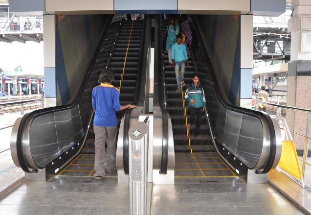
Above: An estimated 43,000 passengers use the escalators at the Secunderabad (India) railway station every day.
These first escalators were followed by twenty more over the next four years and by the mid 1920s, the escalator became well established.
Between the Wars, many escalators were installed to replace older lifts and since that time, the escalator has been established world-wide as the preferred method of high volume transportation of passengers between levels, particularly on busy metros and suburban rail systems.
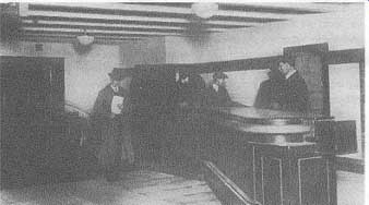
FIG. 1. An early underground escalator.
4. Passenger flow to and from escalators and/or lifts
Again reference should be made to Section 2 on station planning but a little more is given here. At street or station concourse level, when the tracks are at a lower level, passengers tend to arrive at a steady rate unless they have arrived there by another mode of transport.
At platform level, however passengers arrive in large groups as they alight from stopping trains. Passengers can only board lifts or escalators at a finite rate, and in the case of lifts, only when there is a car at the landing.
It is essential therefore that station layouts provide for generous landing areas with capacity to hold large numbers of passengers who are waiting for vertical transportation. For these reasons, large unobstructed landings should be provided at both concourse and platform level, particularly the latter.
Where possible, two alternative means of access to platform level should be provided so that if a machine is out of service at one access point, the other is still available. Multiple access of this type is often found at surface or shallow depth stations but it is very costly to provide this at deep level 'tube' stations.
Where escalators are installed, it is preferable to have three machines in one shaft so that up and down service can be maintained even if one machine is out of use. At stations where there is a 'tidal flow' situation, the three-escalator arrangement also gives an opportunity to reverse one of the escalators at mid-day to give higher capacity with the larger flow. Similarly, this arrangement also helps to keep both up and down service going when replacement of the machines becomes necessary.
Lifts should always, if possible, be installed in pairs, partly to ensure continuity of service in the event of breakdown but also to allow transfer from one car to another in the event of failure between landings.
Failure of an escalator does at least allow its continued use as a fixed stair, albeit at a flow rate of about a third of a moving escalator. However, failure of a lift means that the capacity is lost completely, apart from possibly using adjacent spiral emergency stairs.
5. Achievable flow rates for modern lifts
Passengers get a strong perception that lifts, particularly large and deep ones, are slow and inefficient. This is largely brought about by the fact that there is usually a wait for the car to arrive at the start level, another whilst it fills and a further period of inactivity on the part of the passenger whilst it travels to the required level. Escalators however at least give the impression that there is no waiting for arrival or departure and the passenger can even shorten the journey time by walking up! Passenger flow when using lifts depends upon the size of the car, the height of the rise, speed of travel and the time at the landings.
A medium sized modern station lift car carrying say 32 people might take about 30s dwell time to empty and fill at landings and would travel at a rate of about 1.5 m/s. In a shaft 35 m deep, the effective round journey time of one car would be about 1.4 min. This would mean that running at capacity, a pair of such lifts could transport about 2750 passengers in an hour.
The flow capacity for this lift arrangement would therefore be only about 46 passengers per minute on average. As all lifts have to go both up and down, capacities must be the same in each direction.
6. Flow rates on escalators
If every step of an escalator could be occupied with two standing passengers, it is possible in theory to produce an absolute maximum flow on an escalator of over 200 passengers per minute.
Research has shown that, in fact, this is not possible in practice, even under the most crowded conditions. A number of psychological factors come into play relating to the behavior of people when crowded together which causes some spacing out to be inevitable. In the most crowded and stressful situations when passengers are hurrying to get out of a station, full scale tests and observations have shown that the maximum possible flow rate that can be achieved is between 120 and 140 passengers per minute.
Even with this high rate, there must be clear space at the top of the escalator to allow people to be able to clear away quickly from the escalator to allow following passengers to be able to step off safely.
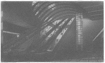
FIG. 2. A modern railroad design using escalators and lift.
For designing stations, it is recommended that a figure of 100 passengers per minute should be used for worst case demand. This means that in normal circumstances, even in peak periods, only one side of the escalator will have standing passengers, the other side being free for those who wish to walk on.
It will be seen from the foregoing that one moderately full escalator can be expected to carry well over twice as many passengers on average than a pair of lifts. Perhaps even more significantly, it will also be realised that two up escalators can easily clear up to 400 passengers from each train running at a minimum headway of two minutes in the peak which certainly could not be achieved by a bank of four lifts.
7. Types of escalators
The escalator basically consists of two continuous chains passing over sprockets at each end and carrying steps. The steps are of approximately triangular cross section and carry a wheel at each comer. The upper wheels are attached to the chain and the lower 'trailer' wheels run independently.
A complex system of tracks ensures that the wheels cannot lift off the tracks at critical points of the escalator.
For all practical purposes, the angle of inclination of all modern escalators is 30".
Escalators that can be used on railroads fall into the following three basic types:
- Compact
- Semi-Compact
- Heavy Duty Public Service
8. Compact type escalators
These are lightweight, low rise machines such as found in departmental stores and shopping malls. The drive machinery is small and installed inside the step band to save space. Access to all the machinery is through the steps and hence the machine can only be serviced during railroad non- traffic hours or when the staircase can be put out of use.
Compact machines can only be of use to a very limited degree on railroads because of these restrictions. They can be useful however for street level to ticket level and overhead viaduct applications, provided there is an alternative fixed stair.
The typical service life of a compact machine is 15 to 20 years at the most. As they are a self contained unit, replacement can be carried out very quickly.
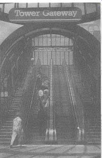
FIG. 3. Typical semi-compact escalator.
Where these lightweight escalators have been installed in certain cities around the world, mainly for access to metros, the author has noticed that they are often out of service. This is particularly the case when the top of the escalators is open to the weather. Clearly they are not designed for heavy use and this must be taken into consideration in the design stage of any railroad.
In any case, it would be wise to involve the manufacturers of these compact machines with the on-going maintenance of these machines on a day-to-day basis.
9. Semi-compact type escalators
These are heavier duty machines than the compact, suitable for light railroads or Metros. They are more robust than the compact type and are suitable for vertical rises up to about 15 m. The drive machinery is too bulky to fit inside the step band and is mounted adjacent to the upper drive sprocket but still within the escalator structural framework which is usually known as the 'truss'. The typical service life of a semi-compact type escalator is 20 to 25 years.
As with the compact type, replacement is easier than with the heavy duty machines as the whole escalator breaks down into a small number of self contained pre-wired and equipped units with a minimum of site assembly.
10. Heavy duty public service escalators
These are heavy duty machines as installed on the London Underground capable of sustained service and carrying crowded loads to considerable heights and depths.
These HDPS escalators have substantial step chains and drive sprockets and a more robust wheel design and mounting arrangement. The truss is wider and deeper than for the compact types and the drive machinery is mounted external to the truss, above the upper drive sprocket, on a separate bedplate. A separately accessed substantial machine chamber is required to house the drive machinery.
The practical maximum vertical rise for these HDPS machines is in the order of 30m, although one exists in Budapest with a rise of 38m. At this height, the total live load can exceed 25 ton which is a great strain on the sprockets, chain and drive machinery.
The typical service life for a heavy duty machine can be expected to be about 40 years although some of the original machines lasted over 60 years before replacement took place. In the last few years, maintenance of these old machines was difficult and expensive however and it is not recommended that modern machines subject to heavy loads should stay in service that long. Also after 40 years, more failures and 'down-time' occurs which badly affects passenger satisfaction and confidence.
The figure below shows a view of a typical heavy duty escalator installed on the London Underground. This is slightly heavier than many installed on other railroads world-wide.
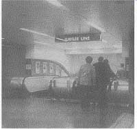
FIG. 4. Heavy duty public service escalator.
11. Typical HDPS escalator dimensions
The following dimensions are given only as a preliminary planning guide.
Actual required dimensions must be obtained from manufacturers.
Min. headroom above step nosings - 2.4 m
Min. length of horiz. steps from comb to intersection with sloped nosing line - 2.0 m
Length of Upper Machine Chamber - 12.0 m
Min. depth of Machine Chambers - 2.5 m
Clear step width between balustrades - 1.0 m
Average o/a width of pair of trusses - 1.9 m
Abs. min. centers of Escalators - 2.5 m
Angle of escalator to the horizontal - 30"
Dimensions for compact escalators are generally much smaller and vary depending upon type and manufacturer.
12. Types of modern lift
There are many types of lift now available today. In engineering terms the most important distinction for railroad applications is between traction and hydraulic lifts.
The traction lift has a car suspended by wire ropes from a sheave or grooved pulley at the other end of which is a counterweight. The lift is moved by a motor and reduction gear driving the sheave. The traction lift is faster in operation than the hydraulic lift, has faster journey times and can cope with any height of rise. The maximum rise that is known to the author in a railroad application is 55 m.
The hydraulic lift movement is provided by a hydraulic ram mounted below or beside the lift shaft, to which the car is attached. Motive power is provided by a hydraulic pump and valve system. Hydraulic lifts tend to be the cheapest and take up less space. The main disadvantages is that they are relatively slow in operation and have a practical maximum rise of about 17 m.
13. Application of lift types
For busy modern stations, vertical transport is better by escalator than lift for reasons given previously. However at less busy or outlying stations or where there are considerable physical site restraints, lifts can be used.
Vertical movement of people in any volume and height above 15 m should always be done by traction lifts with fairly large cars up to a capacity of about 50 people. It is best if possible to provide separate entrance and exit doors at opposite ends of the car to enhance passenger flow at landings.
Lifts for disabled and mobility impaired people are usually much smaller and are hydraulic. It is important that these lifts, although smaller, have wide doorways to ensure that wheelchairs and people with baggage have easy access.
Automatic lifts must have some means of communication from the car to a control room, or at least an alarm that can be operated by passengers in the event of a lift failure or other incident. Wherever possible, lifts should have windows or glazed panels in doors so that passengers can be seen inside the lift car. This is particularly important at unmanned stations and where lifts go from ground level up to an elevated railroad station platform.
14. Safety risks and human factors
When moving people within station areas by mechanical means, there are risks involved which are different from those when all vertical movement in stations is by foot.
These risks need to be faced and steps taken to reduce them to a practical minimum. Also it needs to be stated however, that the risks are not all on one side. If passengers are required to walk or climb unreasonable distances or heights there is the additional likelihood that normal pedestrian falls and mishaps will be increased, to say nothing of the increased distress that could be unnecessarily caused to the aged and less mobile.
Escalators are probably the most powerful pieces of stationary equipment found in most passenger stations and hence are the most potentially dangerous. The main interfaces between moving and stationary parts are likely to cause the most trouble. These include the following:
- Gaps at the sides of steps, adjacent to skirting panels.
- Gaps between steps, especially at the upper and lower curves.
- Combs at top and bottom landings.
- Handrails.
As well as entrapment of passengers at these locations, the main hazards associated with escalator operation are fire, cascade fall, step collapse and step/comb collision.
There are a number of detectors built into modern escalators to reduce these hazards to a minimum. Emergency stop switches are provided on every escalator which immediately slow down and halt the machine as quickly as possible without precipitating a cascade fall for other passengers.
The main hazards associated with lifts are doors opening between floors, passengers entrapped by doors and loss of control of the car speed. Overspeed detectors are fitted to all lifts which slow and stop the lift should any apparent falling or undue acceleration start.
15. Inspection and maintenance
All escalators and lifts must be well maintained and regularly inspected by suitably qualified staff. In the UK, there is a statutory requirement for inspection of lifts and Health and Safety Recommendations for escalators that all machines should be inspected at least every six months. In addition the H&SE recommend periodic examination and function tests of certain critical items at five yearly intervals, notably drive gearboxes and all safety gear.
16. Pumps
Section 6 includes reference to the track drainage system.
On surface railroads, the track drainage collects the surface water and wherever possible channels it either to the nearest watercourse or to Local Authority storm water drains. In rare cases this is not possible or the railroad may itself be subject to flooding or be below the level of the normal water table.
When this is the case, it is usual to drain water by gravity to a holding chamber or sump and, when sufficient water has been collected, it is pumped away to a suitable drain.
Where railroads run in tunnels, water may also percolate through the linings or run down the track drainage to a low spot in the tunnel.
Here again water will be collected and pumped away when sufficient has run in.
Pumps in railroad drainage sumps are often remote from other railroad buildings and may be very inaccessible. They are usually switched on and off by some form of float device which can easily become blocked or fouled by debris, dirt and vegetation.
It is essential that every railroad engineering organization makes clear who is responsible for inspection and maintenance of pumps, sumps, float switches and other associated equipment and lays down the periods when site inspection should be carried out. Because there is some mechanical similarity with lift and escalator equipment, some railroads make their Elevator/Lift and Escalator Engineer also responsible for pumps.
Severe flooding, both in tunnels and on the surface, can disrupt track circuits and signaling as well as causing potential damage to the track structure and must be avoided. Unnecessary delays to trains can be caused by neglect to sumps and pumps and this is a classic case of ' prevention is better than cure'. Certain pump components do deteriorate with time and use. It is essential that proper spares are kept for these either at site or readily available to maintenance engineers.
At particularly vulnerable sites, it may well be worthwhile to install a second standby pump with a separate supply and float switch which will 'cut-in' in the event of the first pump not functioning. Pumps should also be monitored remotely by an alarm in a control room when sump water levels get too high.
Prev. | Next
Top of Page | Article
Index
