1. Stability of earthworks
Most surface railroads involve substantial amounts of earthwork to produce a near as possible level or gently sloping surface upon which to construct the track.
Traditionally in the design of a new railroad, a route and mean level were chosen as far as possible to balance cut and fill. This avoided the need for 'borrow' pits and spoil heaps, at the expense of transporting the excavated material from one cut to another area of filling.
Although this approach is quite sound when considering first cost, it can lead to the use of unsatisfactory materials, unstable slopes and the building in of long term maintenance problems which are difficult and costly to solve. It is vital therefore at the design stage to consider carefully the availability of suitable material for embankments, how these materials should be placed and compacted and at what angle of natural repose the slopes can be expected to be stable in the long term. Proper soil mechanics investigation of the materials excavated in cuttings will determine whether or not they are suitable for transporting to other sites for fill. Railroad embankments require much greater strength than highway embankments since the loading intensity is greater at formation level.
Similarly, cutting slopes must vary in steepness in relation to the natural ground conditions through which the cutting passes. Soil mechanics tests can establish the natural angle of repose of each stratum and the slope must be designed accordingly. These slopes will vary in practice from near vertical in hard rock to flatter than 1 in 3 for the softer clays. Ground water is a vital factor in slope stability. Both in cuttings and embankments, surface water must be channeled to storm water drains or natural water courses. Where drains are either non-existent or blocked, progressive softening of the earthwork structure will take place probably resulting in slipping.
2. Short term considerations
When earthworks are composed mainly of cohesive materials, stability will be ensured in the short to medium term only if a state of equilibrium exists at potential cylindrical slip surfaces. This equilibrium exists when the mass of the material contained above the surface, tending to slide downwards and outwards i.e. to rotate, is adequately resisted by the shear strength of the material.
Design of earthworks should be left to specialists in this area and is outside the scope of this guide. However, all railroad engineers should be aware of the basic mechanics of slope stability and be on the look-out for any signs of moving, particularly in areas where clays, mudstones and shales are present. As well as full failure of slopes, local minor slipping due to erosion can cause track level and line irregularities and needs to be watched and remedied before serious movement develops.
3. Long Term Considerations
Over-consolidated clays and similar soils can deteriorate in the very long term and earthworks containing such materials can fail after many decades of satisfactory service. As has already been mentioned, ground water and the position of the water table can also have a significant effect. When checking stability of slopes in these areas, strength parameters derived from many old failed sites should be used rather than those derived from locally obtained soil samples.
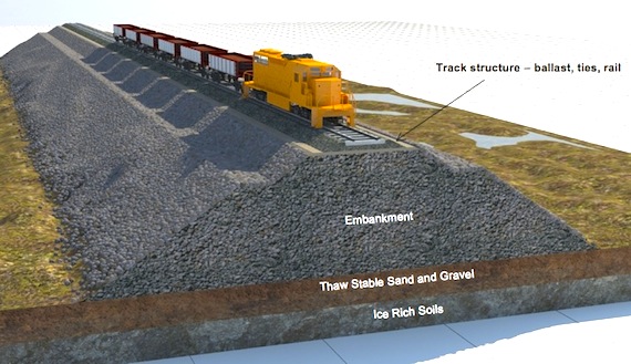
FIG. 1. A well maintained embankment slope.
4. Slips
Any movement of the surface layers of a slope as a body can be classified as a slip. When this occurs, the profile of the slope is changed, usually becoming steeper towards the top and with an upwards 'heaving' of the slope towards the toe of the slope.
Slips in both embankments and cutting slopes can occur for a number of reasons. It is essential that the causes of a slip are fully investigated and clearly established before major remedial measures are adopted.
Immediate measures, like subjecting traffic to speed restriction and/or providing additional temporary support to track, may well be necessary but careful watching of any development is essential in the early stages of any movement.
Local geology needs to be checked, particularly to see if there are any significant variations in shear strength or permeability of materials. Also water level variations and drains need to be checked. Progressive weathering or repeated wetting and drying or freezing may also cause problems in certain stratum.
Other factors that might be associated with slips or be a cause of 'triggering' include the following:
Deep cracks which form in some clays in prolonged dry weather.
Trenches or cultivation close to the tops of cutting slopes or the toes of embankments.
Heavy materials tipped near the tops of embankments e.g. track ballast, or surcharge from plant/materials near the tops of cutting slopes.
Long term ash tipping on embankments causing water pockets to collect in the body of the earthwork, progressively softening the clay beneath.
5. Detection of movement of earthworks
It is rare for large scale movement of earthworks to occur without there being warning signs beforehand. It cannot be too strongly emphasized that in this area, prevention is far better than cure and the object should always be to identify and cure any problems before they develop into emergencies.
Local track staff and others employed about the railroad should be encouraged to look out for and report immediately any of the following:
- Distorted, leaning or dipping signal posts, cable runs or fence lines.
- Tree trunks tipping significantly away from the vertical.
- Cess heave or loss of cess.
- Large cracks in ground surface at any location.
- Local loss of line and level of track which recurs after correction.
Once any of the above 'tell-tale' signs are reported, the local engineer should visit the site without delay and Endeavour to establish by simple observation of the site as a whole whether or not serious movement is occurring or could soon occur.
At that stage, unless immediate action is obviously necessary, it would be wise to drive lines of stakes over the slope area concerned to further establish the degree and direction of movement. If it is suspected that a slip circle failure is developing, a grid of plastic tubes can be placed into the ground over the area concerned in holes pre-bored by driven-in steel pipes.
After a short period of time, the level of the slip surface can be 'plumbed' by insertion of a steel mandrill placed into the plastic tubes. With these simple techniques, the engineer can establish the extent of the potential slip, both on the surface and in depth.
6. Dealing with embankment slips
When an embankment slip is accompanied by loss of material from the cess of the track formation, the top width of the embankment must be immediately made good before traffic can be allowed to recommence. The placing of this fill could well restart movement of the slip unless proper stabilization measures are taken further down the embankment slope.
Although the immediate filling of the lost cess should be in material that is not too heavy, for obvious reasons, care must be taken, if it is porous, not to build-in future problems caused by softening of clay below. Any free draining material placed in this location therefore must be either provided with a drainage pipe system to channel water to and away from the bottom of the embankment, or should be grouted once in position to assist stability and improve surface run-off.
In general terms, embankment slips can be stabilized by one or other of the following methods, or a combination of them:
- Sheet or bored piling
- Berming and/or gabions
- Grouting
- Redraining with counterforts and/or 'herringbone' drains
The selection of the method to be adopted for stabilization of any particular embankment will depend on local circumstances, availability of acceptable filling materials, access for plant and the root cause of the slip.
Piling, whether steel sheet or concrete bored, is carried out in the region of the bottom third of the embankment slope and must be deep enough to stitch the embankment together, across the shear plane of the slip circle.
Berming consists of constructing a small embankment in heavy free draining material against the slipped foot of the main embankment, to act as a counterweight. To be effective, the berm must be placed within the slip circle and as near as possible to its lower extremity. Care must be taken in siting the berm to ensure that it does not block any existing drains or overlie any cable runs or other fixed equipment. Before construction of the berm, vegetation should be stripped from the existing embankment surface to avoid any possible future sliding of the berm on the slippery surface produced by decayed vegetation.
The gabion is a useful device to use in the construction of berms or retaining walls. Gabions consist of wire mesh cages into which is placed heavy broken material such as uniform broken stone or broken out mass concrete. The value of this is that the material is confined and can be placed in an interlocking position and is able to stand at a steeper angle than unconfined tipped material. Gabions are most useful where a substantial stabilizing weight is required where space is limited. They can also be stacked one upon the other. By the time the wire cages fail through corrosion, vegetation, soil and roots will have grown into the gabions ensuring overall long term stability.
Grouting of embankments is a highly specialist operation requiring 'know- how' and specialist equipment. For this reason, railroad engineers who consider this type of ground treatment would be well advised to seek specialist advice, both in investigation and in carrying out any grouting work. It must also be remembered that it is very possible in the early stages of grouting to make the situation worse due to the lubricating effect that grout might have on the slip plane.
This said, grouting can be very effective if properly carried out in suitable locations. The author knows of a number of sites where embankment grouting has been carried out successfully and where embankments with poor history of movement have remained trouble free after grouting for over twenty five years.
Where penetration of surface water into the structure of the embankment is the main problem, attention to drainage often is the best solution.
'Counterforts' should be constructed on the embankment sides at right angles to the tracks. These are trenches with sloping bottoms containing a series of steps and open jointed pipes collecting water and conveying it direct to the bottom of the embankment. The trenches are backfilled with hardcore, broken stone or other large well draining material. Herring-bone pattern side drains are also often placed between the counterforts to intercept surface water and channel it to the counterfort main drains. At the bottom of the counterforts, the drains are connected to a toe drain which conveys the water away to a water course, soak-away or storm water drain.
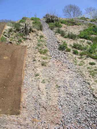
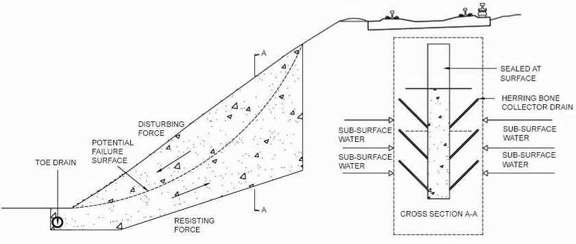
FIG. 2. Counterforts and Herring-bone Drainage.
7. Dealing with cutting slips
When dealing with slips in cuttings, the engineer needs to remember that in this case, unlike in embankment slips, the material that has slipped is likely to have been in its original position from before the construction of the railroad. The cause of the slip will therefore be external to the material.
It is again essential to investigate any cutting movement before major works are put in hand and to understand the reasons for the slipping.
The root cause of a cutting slip is likely to be one of the following:
- Erosion of the cutting face due to weathering.
- Building activities or excavation near to the top of the cutting.
- Tree roots blocking drains or overhanging trees levering cutting surfaces.
- Progressive softening of slopes caused by trapped ground water or water running through porous layers and running down cutting slopes to cohesive strata below.
- Drainage blockages, modifications or sudden increase in flow.
It is often the case that slipping of a cutting will cause upwards heaving of the nearest track which might well be very dangerous for traffic.
If there is room in the cess, short term relief may be obtained by sheet piling or weighting down the bottom of the slip by gabions, but care must be taken not to damage or block drainage. Again, as in the case of embankments, there are a number of techniques that can be used to assist restoration of stability and these are all listed under the section on embankments.
Rock cuttings may present particular problems which may need other treatment. In these cases the sides of the cuttings are often almost perpendicular and trains may be endangered by relatively small pieces of weathered rock falling from above. If this occurs, specialist advice should be sought. Possible solutions include rock bolting, wire meshing, guniting and in very bad cases, construction of rock shelters.
8. Drainage of the trackbed
Usually the trackbed is laid on natural ground that has had the topsoil removed (the sub-grade). If this is the case, the control of water in the trackbed is a major factor in designing the construction layers in relation to the sub-grade material. Materials that are commonly encountered in sub-grades are as follows:
- Non-cohesive materials like gravel and sand.
- Cohesive Clays and slits.
- Organic peats and silts etc.
- Sedimentary rocks like sandstone or limestone.
- Igneous rocks like granite.
- Metamorphic rocks like slate.
- Non-cohesive soils drain well and normally make good sub-grades.
Cohesive soils generally have extremely small pores between their particles and therefore have very low permeability. In this case rainwater falling on the track needs to be collected in the ballast and channeled to drains before it gets to the sub-grade. In the long term, if water is allowed to pond at the cohesive sub-grade, progressive softening will occur and track settlement will begin to show itself.
Peat is a particularly difficult sub-grade to build on and should be investigated by specialists. It has a variety of textures, will usually shrink if drained or if subjected to repeated loading. The behavior of this material also varies considerably depending on the degree of compaction or over-burden it has been subjected to. Wrong treatment of track drainage in areas of peat sub-grade can result in large long term settlements not only of the track but also of adjacent buildings, embankments and fixed installations.
Sedimentary and metamorphic rocks are often permeable by water and often contain springs and lenses or layers of other materials. They are usually much stronger in the unweathered state than cohesive soils and provided that there are suitable means of drainage, will provide a satisfactory sub-grade, even if waterlogged.
Igneous rocks like granite or basalt are hard and impermeable and are unlikely to give any problems as sub-grade for track.
9. Sand blankets
A sand blanket is a permeable layer of fine granular material which is placed immediately over a cohesive sub-grade to act as a drainage layer. To prevent water reaching the cohesive sub-grade, it is recommended to place a layer of plastic sheeting on the sub-grade before placing the sand blanket.
The blanket should be more than 100mm thick with a geotextile layer above it under the track ballast.
The term 'geotextile' means a permeable woven fabric-like material made from polymerized resins as used in civil engineering road and other construction. In this application, the geotextile layer is designed to act as a separator to prevent ballast particles entering the blanket. The sand used for blankets should be nominal '3 mm down sharp' or 'angular' with at least 80% passing the 2.36 mm BS Test Sieve and not more than 4% passing the 0.075 mm sieve. The sand should not contain any very fine silt or exhibit plasticity.
10. Side or 'Cess' drains
The top surface of the sub-grade should be dressed off to a slope of not flatter than 1 in 25 from the center down to the cesses so that percolated surface water will flow to the cess drains.
Drainage systems which collect surface water from the ballast should be placed at a minimum depth consistent with avoiding ponding of water in the ballast or in the sand blanket. Tests have generally indicated that about 80% of rainwater reaches side drains direct via track ballast, the remainder penetrating to lower levels and/or the sand blanket and almost all of the rain will reach the drains within an hour of falling.
Cess drains run parallel to tracks and are usually either open jointed glazed earthenware, galvanized corrugated steel or perforated PVC or polypropylene. The side drains should be surrounded in ballast or other free draining material. They must be laid to a sufficient fall to ensure free flowing and provided with catchpits at intervals not longer than 30 m, required for rodding purposes. The catchpits should have removable top grills to allow removal of silt and their sumps must be at least 450 mm below the level of the lowest drain.
11. Center drains
Where there are more than one pair of tracks, it may be necessary to have a drainage run in the 'eight-foot' between the two pairs of tracks or even in the 'six-foot' on a single pair of tracks where very wet conditions can occur.
In this case, the drains will be similar to cess drains and will also require similar catchpits. It may be necessary to relocate some sleepers or even cut some short to accommodate these catchpits. Center drains should be piped to cess drains wherever convenient.
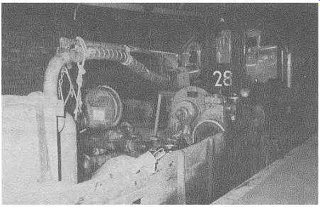
FIG. 3. Pump train for catchpit clearing.
12. Drain cleaning
All drainage pipes must be regularly inspected and rodded when necessary.
This consists of pushing rods through pipes with a 'badger' OF wood block on the end which is a loose fit to the bore. The rods are flexible with screw threaded ends and further sections are added as blockages are pushed to the next catchpit or manhole. Water jetting or winch-operated cleaning tools can also be used where rodding is not successful.
Catchpits must be cleared out regularly to avoid pipe outlets becoming silted up.
It is always wise to inspect all drainage soon after heavy rain, or if possible during a heavy downpour as it is then that any problems will be best observed.
Permanent way drains often discharge into streams, ponds or other watercourses outside the railroad boundary. It is wise in these circumstances to inspect these points of discharge to ensure that they have not become blocked.
Where railroad drains discharge into storm water drains, arrangements must be made with the appropriate water authority to periodically inspect the out fall and to ensure that any 'back-flaps' or other devices are properly working to ensure that no backflow can occur onto the railroad in flood conditions.
13. Ineffective drains
However well laid, drains cannot perform their full function if water is not able to reach them. A drain may, on inspection, be apparently in good condition but not taking water from the ballast. If this is the case a full investigation of the ballast content and condition must be carried out as it is likely that it has become clogged, silted or clayed-up over a long period of time. If the ballast has become impermeable in this way, it is usually necessary to replace the ballast as soon as possible. Where drains are deep, it may be helpful to supplement by the addition of shallow collector drains.
In clay soil, the porous filling around drains may also need to be replaced and the collars of open jointed pipes may need to be opened out and cleared periodically.
Occasionally pipes break and cause blockages. This will usually be discovered when rodding is difficult or impossible at a given location. This situation must not be left or it will progressively deteriorate over a period, possibly causing extensive damage to the track structure. When blocking cannot be cleared by rodding, there is no simple alternative but to investigate further by opening up from the surface.
14. Railroad fencing
In most developed countries, railroads need to be fenced off, both to define ownership boundaries and to keep animals, children and would-be trespassers away from the tracks.
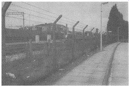
FIG. 5. Fence for third/fourth rail electrified railroad.
In the UK, all railroads must be fenced with a sturdy barrier to a minimum height of 1350 mm. On railroads which have third and/or fourth rail electrification, the fences must be of the 'unclimbable' type such as chain link, weld-mesh or wire mesh. Care needs to be taken at footbridges and other locations where handrails and footholds occur that the unclimbable fence is taken up a clear 1350 mm above such levels.
Arrangements must be made for regular inspection of all fences and urgent attention given to any defects that are reported. In addition to periodic fence inspections, all staff who walk or patrol the track must be specifically instructed to look out for and immediately report any defects seen during other duties and any cases of trespass or straying by animals.
It is only with such vigilance on the part of all staff on or about the railroad, that serious incidents and accidents can be avoided.
All structures over and under railroads must be provided with adequate parapets as defined and stipulated by various authorities. It is essential that fences adequately link with these parapets in such a way as not to leave any gaps or foot holds for access onto the railroad. Any authorized gates through the boundary fence for use of railroad staff must be properly locked.
Prev. | Next
Top of Page | Article
Index
