1. Early railroad structures and materials
The building of railroads always involves the construction of structures, both to support the railroad and its infrastructure, and to carry buildings, roads and other forms of transport over or alongside the railroad. As well as this, many stations and ancillary buildings involve complex structures, sometimes spanning large distances or covering a considerable area, as in the case of a large terminal station.
Early railroad engineers used materials and structural forms which had been well tried in other industrial buildings and transport systems. This included, in particular, brickwork, masonry, timber, cast and wrought iron, generally in the form of massive gravity walls, arches, simple beams and latticed or trussed structures.
Although heavy timber work was used for early load bearing structures, notably trestle viaducts, this deteriorated quickly and was largely replaced by more permanent materials by the end of the nineteenth century.
Cast iron proved to be a good material to use in conditions of direct compression but was found to be unreliable in flexural bending in the tension zones. After a number of accidents which caused bridge collapses in early days, cast iron was banned from new bridges in areas of tensile stress.
Riveted wrought iron however performed well over a long period of repeated loading and was very satisfactory in both compression and tension.
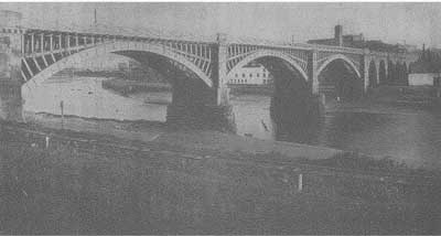
FIG. 1 Wooden (timber) arched bridge.
This material was used for all bridge members subject to bending up to the end of the nineteenth century when steel making was perfected.
Where there was sufficient construction depth available, the well tried arch form was used for many bridges both over and under the tracks. Provided that the materials are sound and the structure is well maintained, the expected life of an arch structure is almost indefinite, even when subjected to dynamic live load.
Cast iron arches have satisfactorily carried railroad loading for periods in excess of a hundred years. In this case the stresses are mainly direct compression, although some tension can occur on skew bridges which require regular examination. Where tension stresses do occur in cast iron arches under dynamic rail loading, which can only be ascertained by strain gauge readings, urgent action is required. The cast iron has to be relieved of live load, either by provision of steel undergirdering or possibly by complete encasement in reinforced concrete. In extreme cases, such as at Kilburn illustrated below, complete reconstruction is necessary.
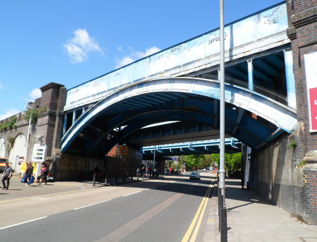
FIG. 2. Hundred-year old cast iron arches.
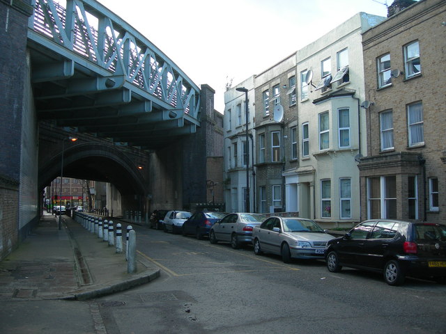
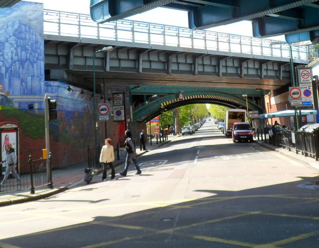
FIG. 3. Reconstructed girder bridges.
Many wrought iron structures were very intricate with complicated riveted connections. These connections were often very inaccessible and could not be properly inspected or painted resulting in pockets of corrosion.
Bearings to large wrought iron structures often similarly could not be properly maintained and sometimes became virtually fixed. This induced undesirable stresses in the structures in extremes of temperature and put extra forces on supporting substructures.
2. Modern welded steelwork
Since the beginning of the twentieth century, structural steel work has been used for the vast majority of metal bridges, both over and under the tracks.
Originally hot riveting techniques, established on wrought ironwork, were adapted and refined for steelwork. Until the early 1940s, all steelwork was shop fabricated using riveting and joined on site using a mixture of site riveting and bolting either with 'black' or turned and fitted bolts.
During the Second World War, welding techniques began to be used and by the early 1950's metal arc welding became the standard method of fabricating structures in the works. Site jointing by then had also improved with the introduction of high strength friction grip bolts which were tensioned by a measured torque. Site welding was also used on occasions but only under very strictly controlled conditions.
Modern welded bridge design also aims at keeping all details as clean and simple as possible. This is not only for aesthetic reasons but also to ensure that maintenance and inspection are made as easy as possible and that rain water runs off without collecting in corrosion pockets.
For medium spans, steel bridges are usually constructed with single webbed '1' section main girders either under the track or alongside with cross girders between to transfer track loads back to the main girders. Care needs to be taken in the design of the connection between the cross girders and the main girders to ensure that the joints are well protected against corrosion.
For longer spans, welded steel bridges are often constructed with main girders in the form of a box. Again, these can be placed either immediately under the track or alongside in a 'through' formation. The advantages with box construction are that it is torsionally much stiffer than an 'I' section, can have very clean lines and can have access hatches to inspect the inside of the box which is protected from corrosion.
For double track railroad bridges with much larger spans, in excess of about 30m, the main girders can be in the form of a lattice or truss.
Again, with welded construction attention to detail in the design can result in a very clean design which is far easier to maintain than with older riveted trusses.
Painting methods and preparation need to be very carefully considered on all new steel structures.
On all types of modern welded steel bridges it is essential to ensure that there is good access for inspection and maintenance of main bearings. All bearings should be on concrete plinths to ensure that jacks can be placed alongside to relieve the loads to allow replacement of bearings if necessary during the life of the structure.
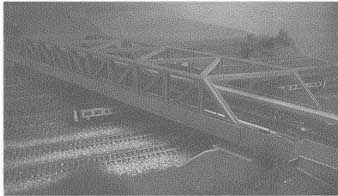
FIG. 4. Welded truss railroad bridge.
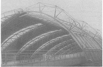
FIG. 5. Welded tubular station roof at Waterloo.
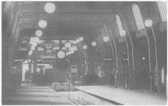
FIG. 6. Reinforced concrete station portal frame built in the 1930's.
Station roofs can be constructed in welded steel. For long spans, one of the best forms is welded tubular steel. Again, much care needs to be taken at the design stage to ensure that joints are simple, clean, inspectable and without pockets to collect water. Thought should also be given on large roofs to the proposed method of cleaning of gutters, downpipes and any glazing, and method of inspection and painting.
3. Reinforced concrete structures
Mass concrete structures and foundations were in use well before the construction of the first railroads. Even the Romans were well versed in the use of cements to bind together natural and manufactured materials and used mortars and mass concrete in many 'gravity' structures.
In such structures, loads were assumed to spread at an angle of about 45", thus avoiding tensile stresses within the concrete mass. Even in the late eighteenth century it was known that concrete was about ten times stronger in compression than in tension.
About the middle of the nineteenth century, a number of systems of reinforced concrete were introduced in France, notably by Monier and Hennebique. By the early twentieth century, reinforced concrete was being used in the UK for railroad structures to an increasing degree.
In essence, reinforced concrete combines the compressive strength of concrete with the tensile resistance of mild steel reinforcement. Structures are subject to stress analysis under all combinations of likely loading and the steel reinforcement is introduced where tension will be produced by bending moments, torsion or shear forces or a combination of these.
The main advantage claimed for concrete over steel is that there is no corrosion and the structure does not require painting or maintenance.
Although there is some truth in this, it is not the full story. Minute cracks do occur in concrete. These may be caused by shrinkage at the time of casting but proper safeguards during concreting and in the immediately following curing period can reduce these to an acceptable minimum.
Flexure of the structure under load may also produce some cracking of the cover concrete to allow the steel to pick up the tensile strain. Here again following certain design requirements laid down in BS Codes of Practice should reduce such cracking to an acceptable minimum. In exposed locations however, over a number of seasons and climatic variations, it is likely that some moisture will penetrate the surface of reinforced concrete structures.
This must be carefully watched as corrosion of reinforcement under apparently sound concrete cover can seriously damage structural integrity. Structures subjected to dynamic loading and/or reversal of bending moments (as on continuous beams) need to be particularly carefully inspected on a regular basis.
Reinforced concrete is particularly useful for structures carrying mainly dead or static loads, such as columns, retaining walls, pile caps, spread foundations, rafts and piers where the dead weight of the concrete in the member under consideration is not too significant.
Where reinforced concrete has been used for long span structures carrying only a relatively small amount of superimposed load e.g. snow and wind, the extra dead load produced by the reinforced concrete structure coupled with the need to control and counteract cracking has often made it uneconomical in the long term. Long span station roofs and footbridges in reinforced concrete can often come into this category. This is the case even after allowing for savings arising from the fact that no periodic painting is required.
Simple components which are not subjected to excessive loads or moments are often very satisfactorily constructed in precast reinforced concrete. These include components for platforms, staircases, subways, cable ducts and runs, walkways, fence posts, sand bins, catchpits and small lineside cabins.
On modern railroad bridge superstructure construction, reinforced concrete is often used in conjunction with welded steelwork or prestressed concrete as part of the bridge deck and often forms the parapets.
Reinforced concrete is usually used today in the substructure, abutments and wing walls in place of mass concrete, brickwork or masonry, purely because it is more economical in both materials and excavation costs.
Early reinforced concrete was compacted manually and often was laid with too wet a mix resulting in poor density. Today careful control of the water/cement ratio and compaction by mechanical vibrators ensures a stronger and more dense and durable material.
4. Prestressed concrete
Concrete is about ten times as strong in compression as it is in tension.
Reinforced concrete simply overcomes this deficiency by adding steel reinforcement where tension is likely to occur. Although this is completely satisfactory, it does lead to heavy structures as up to half of the concrete is not contributing to the structural strength. This is particularly so on long span structures or where reversal of bending is likely under dynamic loading.
This disadvantage is largely overcome by the introduction of prestressing.
Simply put, this is a technique of introducing a pre-compression into the concrete in areas where tension would otherwise develop under loading, which is at least equal to the applied tension, thus negating that tensile stress. In this way, the whole concrete section remains under compression and therefore 'works'.
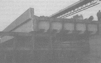
FIG. 7. Railroad bridge reconstructed using pre-tensioned prestressed
concrete beams.
In general terms, there are two methods of introducing prestress to a concrete member. The first is known as 'pretensioning'. This involves applying tension to wires which are set into a mould and then concreted in. These wires or strands are fully bonded to the surrounding concrete and once the concrete has hardened and acquired sufficient strength the wires are cut thus applying a compressive force to the surrounding concrete. This method is usually applied under factory conditions and is largely used for small repetitive units like beams, sleepers, planks, ducts and lintels etc. It is also often known as the 'long line' method of prestressing.
The second method of prestressing is more often used for larger units and is known as 'post-tensioning'. As the name implies, in this method the tensioning is carried out after the casting of the concrete. Units are provided with cast-in ducts and anchorages and the prestressing tendons are stressed up once the concrete has achieved sufficient strength and then held in tension by some form of wedging at the anchorages.
With larger beams, it is quite common for segmental units to be cast in a transportable size and stressed together on site. After tensioning of the prestressing tendons, the ducts are usually fully grouted up under pressure with cement grout. The joints between the precast segments are usually filled with an epoxy mortar or can be left dry if they have been carefully cast against one another in the works thus ensuring accurate fit.
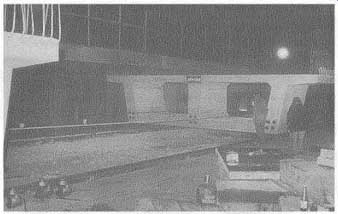
FIG. 8 Concrete segmental box girder units.
Epoxy mortar can be used in a variety of ways with concrete and other structural materials where early strength is required. One disadvantage, however that must be watched, particularly when working at night or during possessions, is that certain materials will not 'go off at low temperatures.
Prior advice should be sought from manufacturers on the lowest air temperature that will allow the proposed materials to set before using in possession.
5. Bridge reconstruction
For new railroads, methods of construction of bridges and other structures are very similar to those adopted for any other civil engineering project.
On existing railroads however, the design and construction methods that have to be adopted are largely dictated by the absolute requirement to continue to operate trains safely during the construction period.
Superstructures for bridges and structures, both over and under railroad tracks, need to be constructed during possession of the railroad, at night or week-ends when railroad traffic is at its lightest Often, it is possible to carry out work on substructures during railroad traffic hours but this often involves prior construction of temporary or protective works during possession of the tracks. The conventional method of reconstruction of abutments is to install 'waybeams' under possession to carry tracks in the immediate area of the new abutment. These waybeams can be supported on timber cribs or pads or piles. This then allows construction of the new abutment beneath, although it is usual to impose a speed restriction on trains crossing the temporary works.
Various other methods of construction of substructures have been adopted, avoiding the use of waybeams. These mainly relate to various methods of jacking precast units into position laterally from jacking pits on either side of the track. Smaller units can be thrust into position using similar pipe-jacking or thrust-boring techniques. It is also possible to construct deep pile foundations on either side of the track and incorporate cill beams in the superstructure that will carry the loads onto the side piles.
Where large span railroad bridges have foundations in tidal waters, thorough investigation must be made into the condition of foundations and the various alternative methods that are open for reconstruction and/ or strengthening.
Superstructures for railroad bridges on existing lines can be placed in position by one of the following basic methods:
- Piece-small lifting in
- Complete lifting in
- Lateral rolling-in or sliding-in
- Wrap-round
- Launching
- Tailor made method e.g. Lune Viaduct
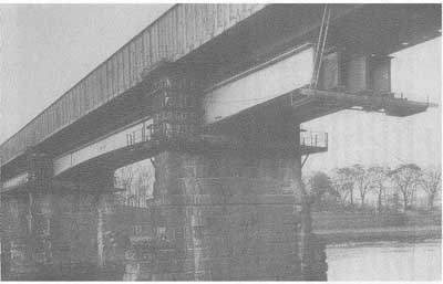
FIG. 9 Erection of new girders, in line viaduct.
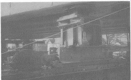
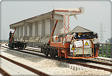
FIG. 10: 100-ton rolling-in trolley.
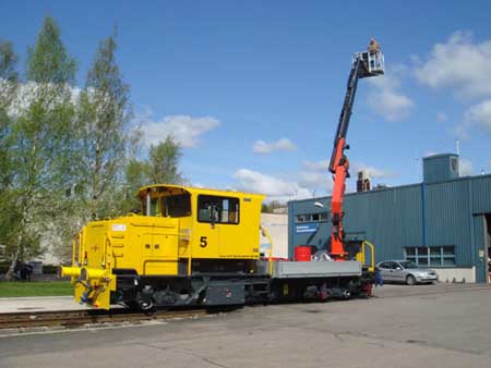
FIG. 10a: Railbear trolley on the Helsinki Metro: the trolley is equipped with a Palfinger special crane and a workman basket.
Lateral repositioning of bridge superstructures --as for many decades been done using steel balls running in the web of bullhead rail. The rolling-in trolley usually incorporates a one hundred ton capacity jack and the lateral pull to move the bridge is provided by cable winches, either manual or power driven. In recent years, heavy bridges have been slid into position rather than rolled using skates surfaced with PTFE. This is a very slow operation but can be carefully controlled and bridges weighing well over a thousand ton have been moved into position using this method with a possible positional accuracy within 15 mm.
In this method, large bridges are usually moved into position about 100mm higher than their final level and then jacked down once in the correct location on plan.
Rail mounted rail cranes are available for lifts of units on most main line railroads. These are usually limited in capacity to not more than 75 tons at minimum radius and may be required at short notice to deal with derailments or other emergencies.
Where it is possible to get road mounted cranes to the site of the work, these are often of more use due to their flexibility in operation and increased capacity and reach. It is now possible to hire road cranes with a capacity of up to 500 tons, or even more.
Special precautions need to be taken when using both road and rail cranes on railroads having overhead electrification.
6. Brick and masonry structures
Many early bridges over and under railroads were constructed in brick or masonry, usually adopting some form of arched construction. The methods had been well tried over the preceding centuries on the building of roads, canals and aqueducts. Today, there are still examples of such structures built almost two thousand years ago by the Romans, that demonstrate the basic stability of masonry arches.
Railroad bridges constructed both over and under tracks incorporating arches usually last as long as the railroad and will only be demolished if widening of the span is necessary or higher headroom is required for overhead electrification.
The experience gained in carrying out such arch demolitions on British Rail prior to electrification, showed the high intrinsic strength of most arches. The only occasional exception to this is on skew arches or those which are very flat, as one might expect.
A prerequisite for long term stability of an arch is unyielding supports and foundations. Many perfectly sound arches have collapsed due to movement of other parts of the main structure, foundations or supporting ground. It is imperative therefore that much care is given to both design and maintenance of all supports when adopting any form of arched construction.
Masonry and brick gravity walls, abutments and piers similarly can continue for very long periods without much attention. It is important to keep joints well pointed and any drainage well rodded to ensure that water does not get into the structure. Such percolation of water can cause deterioration, particularly due to frost action and washing out of 'fines'. In very large masonry piers it is wise to check internal condition by trial bores at different levels. Any voids that are found or softness of material should be pressure grouted to prevent further deterioration.
Because of high labor costs, it is not usual today to use masonry or brickwork for large gravity structures. If appearance is a consideration, structures can be constructed in concrete and then faced in brick or masonry.
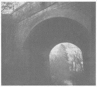
FIG. 11 Brick Arched Underbridge still giving good service after 150
years.
7. Examination of structures
All bridges, structures and buildings which form part of the railroad infrastructure need to be carefully inspected at regular intervals by suitably qualified and experienced staff. Most railroad authorities inspect in detail all bridges and other structures which are subjected to dynamic loading at least every four years, as well as carrying out superficial inspections on an annual basis. Any matter that comes to light in either the annual or detailed inspection may mean that the structure is subjected to special inspection at more frequent intervals.
The aim of the annual superficial examination is to bring to notice any significant deterioration in condition, any development of new cracks or worsening of old cracks, any sign of impact from vehicles or serious vandalism, walls out of plumb or similar developments which might place the railroad at risk. Whenever possible the structure should be observed under traffic to note any undue vibration, deflection, looseness or separation of parts and to observe its general behavior.
In addition to the inspections carried out by specialist examiners, permanent way patrolmen and others walking about the railroad should be instructed to report any defect or change to condition that is noticed on structures.
Each railroad authority must devise its own method of numbering all structures and recording inspections and work carried out thereon. Records must be kept up to date and always available to responsible people who 'need to know'. Where possible, such records should be kept on computer with back-up records kept at separate locations in case of loss by fire, theft or vandalism etc. The unique number that is given to each bridge or structure should be displayed on at least two number plates fixed permanently to the structure.
Some railroad authorities number each line with a pre-fix letter e.g. MR90 (bridge number 90 on the former Metropolitan Railroad) or by referring to the location from the main terminus e.g. 96M 20 ch (bridge 96 miles 20 chains from Paddington) or give the line and then the number e.g. London-Birmingham No 59. Care needs to be taken, especially at intersections of railroad lines that all structures are given a unique number and that there is no duplication. This is particularly important where new bridges are built over existing lines or where old structures are modified or removed. When a new structure is completed, it is important that 'as-built' drawings are provided to the inspection office and that contract or design drawings are not assumed to be as actually constructed on site. This should be the prime responsibility of the resident engineer on any project before matters are finally wound up on site.
8. Structural maintenance
As in many other areas of railroad engineering, proper maintenance of structures is essential if they are to be kept in satisfactory service for a maximum period.
As mentioned previously, regular inspection of all structures must be programmed and from this, maintenance schedules should be drawn up.
Certain maintenance works such as painting of steelwork, gutter cleaning and drain rodding should be carried out on a regular cycle basis. Other work will largely rise from inspection and will be on an 'as-and-when' basis. This would include such items as brickwork repairs and re-pointing, bearing replacement and minor steelwork repairs.
Structural maintenance work can be dramatically reduced in cost by attention to detail at the design and construction stage. Good examples of this are ensuring that bearings can be properly inspected and replaced without costly temporary works to support the bridge and the reduction of corrosion pockets to a minimum. Similarly, good inspection procedures should ensure that potential weaknesses are spotted and dealt with at an early stage before too much damage takes place.
9. Strength assessment
Running in parallel with proper maintenance and inspection procedures, all railroads need to have a specialist team engaged upon assessment of strength of all existing structures. This involves what may be described as a 'designing backwards' exercise.
Bridge Assessment is made necessary by the general increase of loads being carried by highways, the variation of loading on railroads as speeds increase and axle spacings widen and the general deterioration of some structural materials through age.
Based upon the condition survey which arises out of the four yearly detailed inspection, engineers can calculate the likely stresses that will occur under maximum loading at critical points. Site measurement of remaining metal coupled with testing to destruction of samples taken from non-critical locations on the structure or certain non-destructive tests will then allow accurate analysis of the actual residual strength of the structure.
Any resulting calculated overstress will then be carefully considered to see if any relief can be obtained to critical members by local strengthening or propping or by imposing speed restrictions. If none of these measures are acceptable or effective in the longer term, then consideration must be given to reconstruction.
Link: BridgeOfTheWeek.com (Los Angeles)
Prev. | Next
Top of Page | Article
Index