Constructing, maintaining, and improving the surface condition of the tracks is the job of specially designed surfacing equipment. They include tie machines, spike inserters, rail heaters, tampers, and ballast regulators. These are the machines that put the ties, fasteners, and rail in place, and gauge, level, and even out the running surface track.
Inspection and Preparation
Railroads often schedule tie replacement in conjunction with surfacing activities, such as tamping and ballast renewal. Ties are designed to last at least 20 years under normal conditions, and it’s not unusual for them to survive 40 years or more in regular service. While the ties last a long time, they don’t last forever. When ties begin to disintegrate, they lose their ability to hold spikes and/or fasteners properly and keep the track in gauge. Tie spacing and the number of good ties for a given section of track are central factors in classifying track and determining maximum speeds. Every tie need not be in tip top shape for track to function properly. Ties are often replaced one at a time by a tie gang working with a host of small machines, but are sometimes replaced en masse by gigantic automated track machines, or by simply installing new track in sections or panels.

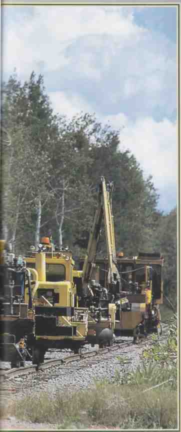
ABOVE Looking like an army of gigantic mechanical insects heading off
to work, Wisconsin Central tie inserter/extractors and tie cranes work
along the Ladysmith Subdivsion in September 2000. The machine in front
is a tie inserter/extractor.
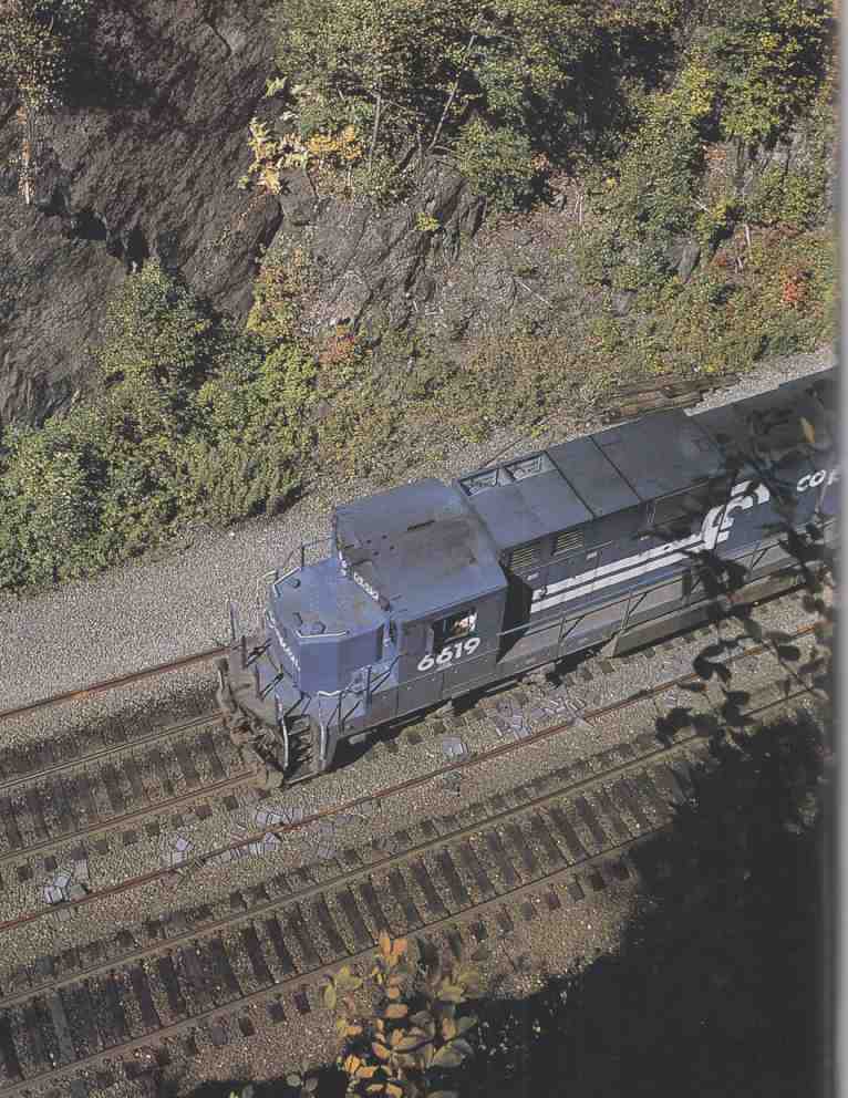
ABOVE: Prior to track maintenance or installation, a work train will come
along and deposit needed materials along the right-of-way. Here at Middlefleld,
Massachusetts, a Conrail train has laid out new continuous welded rail
and fresh tie plates in preparation for work by a steel gang.
In preparation for track work, a railroad official in charge of maintenance will survey the tracks, taking careful note of what kind of work must be done. On mainlines, an official will often be aided by the reports issued by track geometry and track defect detection cars. On secondary lines, the official will need to use traditional judgment in his track survey.
Walking along the track, the official will make close observations about the condition of ties. Are they solid and holding the rails properly? Or are they showing signs of age and decay? If the spikes that hold the rail have become loose, or the tie plates have been forced into the tie, these are signs that the tie needs to be replaced. It may have cracked or broken because it was center- bound, or it may have damaged ends; both are the result of ballast problems. In some cases a minor derailment may have torn up the tops of ties, resulting in enough damage to warrant their repair. On lightly used yard trackage, ties may have disintegrated to the point where they have completely lost their function altogether.
A survey will also assess the condition of rails and joints. The joint is the weakest part of the track structure, and bad joints can cause a variety of problems. They can lead to damaged rails, or contribute to difficulties with pumping and drainage. The use of continuous welded rail in place of conventional jointed rail on most modern mainlines has saved the railroads a lot of maintenance work. But welded rail has its own set of potential problems. It requires more rail anchors, which are needed to keep the rail from sliding, especially in places where trains commonly brake and stop. Welded rail in particular has a propensity to slide, and sliding rail can damage track. In addition, welded rail is more susceptible to expansion problems, such as heat kinks, caused by changes in temperature. To keep welded rail in place, even during extreme temperature swings, it must be tightly secured by spikes, anchors, and other fasteners. A good track surveyor will know what to look for when assessing the condition of welded rail. If there are signs of rail movement, such as scrape marks where the spikes contact the rail, or ties that have been pulled diagonally out of position, the rails have been moving and the track re quires attention.
During the course of the inspection, the track official will decide which ties and rail sections need replacement, determine the variety and amount of replacement ties and rails required, and note where they should be laid out along the line. To make maximum use of track maintenance windows, the railroad and track official must have a well-formulated plan of attack. Insufficient or in appropriate materials left at trackside can cause costly delays.
Tie Gangs
Before the advent of mechanized equipment, ties were replaced manually by section gangs Hand tools such as track jacks and rods, that were also used in tamping were employed for tie removal, along with more specialized equipment such as tie tongs. While some maintenance is still done manually today—especially in situations where modern expensive machines are impractical or uneconomical—most tie replacement is accomplished with some level of mechanization. A variety of machines are manufactured for removing old ties and delivering, positioning, and inserting new ones. There are also different machines for just about every stage of work involved in placing, in and/or removing rail fasteners, anchors, and tie plates.
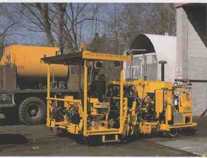
---ABOVE The Fairmont-Tamper dual spike puller has two sets of operator controls,
one for each side of the track. Fairmont-Tamper is now part of Harsco Track
Technologies, which manufactures a whole line of spike pullers and spike
inserters.
A tie gang encompasses a dozen or more machines, all working in tandem with one another. Each machine will have its own operator, with some machines requiring two operators. Although independently controlled, the machines work together as part of a highly coordinated team. Every machine has a specific assigned task that must be performed in a predetermined order in conjunction with the other equipment.
Tie work is often done as part of a line rehabilitation, so the tie gang will usually work over the same section of track for days at a time until the job is complete. Whenever possible, a section of track will be taken out of s and the authority to use the tracks is handed over to the track gang to allow them to work uninterrupted for as much time as possible. Since tie work disturbs the track structure, it is preferable to have each stage of the job completed as quickly as possible before trains are allowed to operate on the track again. The work may be accomplished in stages, and if trains need to use a section of track before it has been brought back up to go standards, ‘slow orders” may be assigned over the repaired section. This is especially true where complicated surfacing work, such as ballast cleaning, undercutting, and other work to the roadbed is being done in conjunction with tie work. This complex track overhaul requires the tracks to settle properly before trains are permitted to operate at top speeds.
A Day Out with the Gang
By the nature of the work that is being done, the warmer months are the preferred time of year for tie and rail maintenance in many areas, especially those afflicted by tough winter weather. The tie gangs usually operate during normal working hours, morning to evening on weekdays, in order to take full advantage of daylight. In the morning, a tie gang is brought to the track machines by a company bus. The machines are typically stored overnight out of the way on sidings when they are not in use. It is desirable to get the machines off the main tracks and passing sidings, so they will often be stored on lightly used, some times poorly maintained tracks, which are kept in place at strategic locations along a line for just such work, as well as for setting out damaged cars.
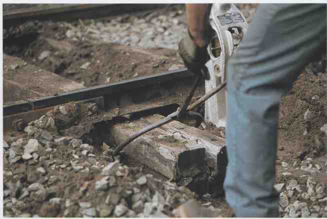
---ABOVE: In the old days, removing rotten ties required jacking the tracks
up with portable hand jacks, digging the ballast away from the tie with
shovels, and forcing the tie out using long steel rods and specially designed
tie tongs. What took a half an hour or more to accomplish by hand now can
be done by machine in a matter of seconds.
At the start of each workday, the foreman and supervisors discuss a plan of action, and the ma chine operators make sure their machines are in good order and stocked with the necessary supplies. Before the gang can go to work, the dispatcher has to be contacted for permission. Sometimes a train or two may need to get over the section of track before work can begin; other times the gang can get track authority right away. Once proper authority has been received, the machines proceed out of the siding and run down the line to the spot where work is to begin. This parade of equipment looks something like an army of giant mechanical insects marching off to war. Often there is some duplication in the types of machines in the parade, as two or three of one type might be spaced apart to speed up the work. By the time the machines have arrived at the work site, tie and rail trains will have laid out the appropriate materials, such as ties, tie plates, spikes, rails, and fasteners. If you see fresh materials along a line, this is a pretty good clue that work is in progress or about to take place.
On track that uses traditional wooden ties and spikes, spike pullers and rail anchor removers will come along and free all rail fastenings from ties scheduled for removal. Likewise, on larger sections, where the rail is to be replaced, fasteners are removed from all the ties on the specified section. Once the fasteners are out of the way, tie extractors, tie cranes, and tie inserters come along and remove and replace the defective ties. In some situations, a backhoe can be used to replace ties, but this is not efficient for large jobs. After the ties and rails have been worked on, the track must be regauged and respiked into place, and rail anchors must be reattached as well. On a modern gang, there are machines to do each and every one of these tasks. When the basic track has been re assembled, new ballast is dumped, and the track is surfaced using ballast regulators and tampers, along with other equipment. If the surface of the track was in good shape prior to the tie and rail work, then simply tamping may be all that’s necessary; if not, the tracks will require alignment as well. Lining is done by specialized tampers, described later on. At the end of the day, the machines proceed to the nearest siding and tie up for the evening.
In some situations, such as on heavily used single-track lines, it is not possible to give a track gang more than a few hours at a time to do their work. In these cases, the gang is limited in the amount of work it can accomplish, and the workers must maximize the use of their time. The gang will zip in to place, get the job done, and then zip out again as quickly as it can before its track time expires. A dispatcher cannot run trains until all the machines are safely out of the way and he has received a report describing any slow orders that may be placed on the track. Occasionally work is delayed if a machine breaks down. Since the machines work together in assembly line fashion, one broken machine can ‘tie up” the whole process (no pun intended).
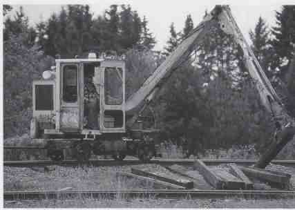
---ABOVE: A typical tie crane features a short wheelbase and a long, hydraulically
controlled arm with a claw at the end for gripping ties. Several of the
ties below the crane have been recently replaced, which is evident by the
missing ballast around the ends of the ties.
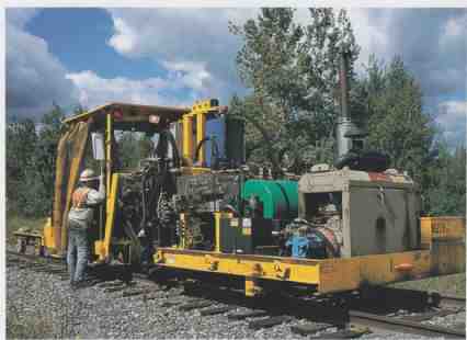
---ABOVE A Nordco spike inserter pauses between jobs on the Wisconsin Central.
This spiker, like most modern track machines, is powered by a diesel engine.
The spike driving machinery is operated hydraulically.
Spike Pullers
Automated spike pulling machines have made the task of spike removal must faster and easier. A typical spike puller is a relatively small, self-propelled machine with a welded steel frame. It has a seat and controls for the operator controls, but it is typically an open-air machine, so that the operator can be as close to the work as possible. Usually there is a roof to protect the operator, and a tarpaulin can be draped over the machine to form a tent in case of rain. Spike pulling is serious work, and the puller is not aimed at operator comfort. A spike puller has a particularly awkward look to it that makes it seem like an erector set project gone awry. It lacks symmetry, and doesn’t have any metal sheathing to disguise the machinery, which is all exposed to the air on the platform. Most modern spike pullers have two heads that allow them to remove pairs of spike simultaneously. A normal arrangement is for one spike to be taken out from each side of the rail. The removal carriage is hydraulically operated, and consists of a tapered guide with small wheels designed to keep it properly positioned over the rail. The puller jaw is made of very strong alloyed steel that is resistant to damage from the act of spike pulling. The operator uses the controls to direct the carriage jaw to pull the spikes out of the tie. Modern machines are equipped with computers that can be programmed with a pattern to assist the operator in locating and removing spikes as quickly as possible. The carriage can be adjusted up and down, left and right, and forward and backward to center the puller claw over the spike.
Spike pullers are usually set up to work on the left or right side of the track. Depending on the type of job being performed, it is common to see two or more spike pullers working together. Since a tie gang needs to remove all the spikes on a single tie in order to extract it from the track structure, spike pullers are usually paired up, each one working on one side of the track. Often more than two spikes are on each tie plate to hold the rail in place. Anchor spikes are used to secure the tie plate and don’t actually come in contact with the rail.
Harsco Track Technologies manufactures a typical dual-action spike puller, the Model W113 Series E. It is just under 12 feet long (11.83 feet), 93 inches wide, 94 inches tall, and uses a 9-foot, 4-inch wheelbase. The machine normally comes with a roof over the operator controls, and a built-in turntable assists with rapid deployment and easy reversal. With these features it weighs 5,380 pounds. Harsco’s spike puller is powered by a 42-horsepower diesel engine that operates at 2,800 rpm (very fast compared with diesel loco motive engines, which normally operate at just one-third that speed) and uses a hydraulic propulsion system with a four-wheel roller chain drive. The main hydraulic system has a working pressure of 3,000 psi.
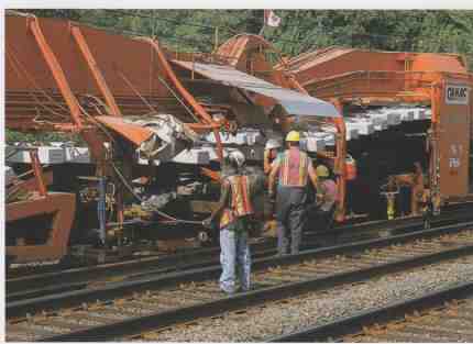
---ABOVE: This mechanized tie relaying machine is designed to rehabilitate
concrete ties and welded rail simultaneously. It picks up the old rail
and ties as it lays down new track, working in a continuous unbroken operation.
Built in 1977, this CANAC machine is working on Metro-North at Green’s
Farms, Connecticut, on July 17, 1999.
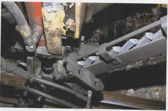
ABOVE: A detailed view of the spike feed chutes on a Nordco spiker. The spikes
drop in the jaw by gravity and are driven in the tie with a swift strike
from a hydraulically powered ram.
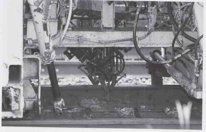
ABOVE: As mechanical jaws hold the spike in place, the ram will drive the
spikes straight into the tie. An automatic spike driver takes the place
of men with heavy mallets that would hammer a spike in manually.
The operator station on the Model W113 Series E has a padded swiveling chair with arm- rests that gives the operator good visibility of the working area. The controls consist of joysticks that enable the operator to direct the spike pulling carriages, and move the machine back ward and forward. Since the spike puller must be able to line up perfectly with the spikes, it is important to have accurate slow speed control. Braking is accomplished with a standard foot pedal arrangement. The brakes themselves are adjustable shoe treads that contact one wheel on each axle. Since the machine has a maximum travel speed of only 26 miles per hour, braking is designed for aligning the spike pulling heads, rather than for coming to a smooth swift stop from high speed.
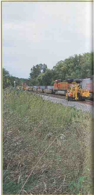
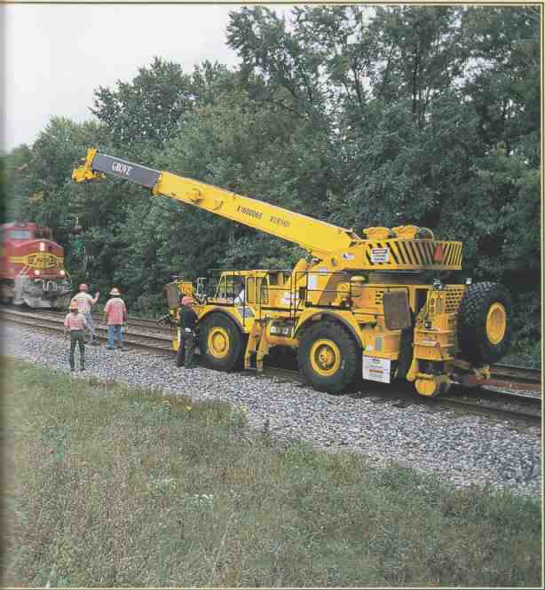
---ABOVE Safe working practices are very important when working on a railroad.
When one track is closed to traffic for a steel gang, the other may be
open, though trains must proceed at reduced speed through the work site.
Here a Kershaw Kribber-Adzer and Grove crane wait for a westbound train
to pass before resuming work on the track.
Harsco’s Model W134 Series A is a bigger spike puller. It carries two operators and is de signed to remove two spikes at a time from both sides of the track simultaneously, eliminating the need for two spike pullers working in tandem. It is set up to allow either operator to drive the ma chine and position it over the ties. The puller jaws can be adjusted independently of the machine, which is necessary to allow both operators to do their work without interfering with the other. The machine is 12.62 feet long, 102 inches wide, and 112.5 inches tall, and it rides on an 8-foot, 4-inch wheelbase. Its engine is significantly more powerful than that on the WI 13 Series E, capable of generating 80 horsepower and working at 2,500 rpm. Unlike the single-operator machine, this one only has two-wheel drive.
Tie Extractors and Inserters
Prior to mechanization, replacing ties was a slow, labor-intensive business. After the spikes were removed, the tracks were jacked up using hand jacks. Long iron rods and tie tongs were used to leverage the tie loose and pull it out of place. Often a fair amount of digging was needed to free the tie from its spot. Those days are long gone, thanks to automatic tie extractors and inserters. Now ties can be replaced mechanically as fast as seven per minute with these highly specialized machines.
A full range of tie extractor/inserters are avail able, ranging from lightweight machines designed for simple jobs, to massive tie-laying machines de signed to rehabilitate whole sections of mainline quickly. Several different companies produce these types of machines. A typical smaller machine used by track gangs that need to replace ties intermittently will be just 14 or 15 feet long, self-propelled, and controlled by a single operator. Since a smaller tie extractor usually works on tracks that will be placed back in service shortly after it is finished, the machine has to interfere as little as possible with the overall track structure. In order to remove a tie, the machine clamps on to the rails, and lifts the track slightly with hydraulic jacks. A hydraulically controlled telescoping boom then grips the tie. From the end and pulls it out. Since ties can become angled, the boom is able to rotate right or left 10 to 20 degrees on axis from a hypothetical perpendicular in order to grab any way ward ties. The boom must also be able to lift as high as 25 degrees above the track plane, and drop up to 15 degrees below the track plane to extract the tie from below the rails. This process involves an enormous amount of force. Even a relatively lightweight tie machine, such as Harsco’s 925 Tie Inserter/Remover, will apply 39,000 pounds of lifting force to the track, and as much as 19,000 pounds of extracting force on the tie.
Larger tie extracting machines use additional tools to speed up the extracting process. For ex ample, Harsco’s RMC305 Series A TKO Tie Remover/Inserter has an optional piece of equipment that pushes the tie from the end opposite the boom. Since some ties can become bound and difficult to extract, this device applies an addition 10,000 pounds of force, which is usually enough to get even the most stubborn ties moving.
New ties are inserted with the same type of equipment that was used to extract them. The tracks are lifted, and the boom grips the new tie and slides it into place. To facilitate the process, some machines use an adjustable arm to guide the tie underneath the rails.
Tie Cranes
A tie crane works in conjunction with the tie inserter, lifting new ties that have been placed along the right-of-way, and laying them perpendicularly across the tracks for the tie inserter to grab hold of. A tie crane may also pull a small trailer with new ties on it. Tie cranes are also used to stack old ties after they have been removed.
A typical small self-propelled tie crane is a relatively lightweight piece of machinery. They weigh in the vicinity of 7 to 9 tons, and feature a remarkable short wheelbase, often just 6 feet long. The crane itself can rotate 360 degrees on a center axis, and may be able to reach as far as 25 feet from the center of the track. In order to lift a typical wooden or concrete tie, the crane usually has a lifting capacity of 800 to 1,000 pounds. It may be equipped with locking rail clamps to keep it from tipping over when lifting heavy loads that are far from the center of the track.
Spike Inserters
Spike inserters, sometimes called spike drivers, come in a variety of different formats. A typical machine used for tie jobs would be a moderately sized dual-headed spike driver that requires two or three people to operate. One person runs the machine and applies spikes to one side of the track, while another operator applies spikes to the other side; the third person supplies the spike chutes with fresh spikes. Although a spike driving machine appears awkward and looks quite complex, its function and operation are actually quite simple. Like other small track machines, a spike driver is self- propelled, with a small diesel engine. A dual-headed machine has a pair of hydraulically or air-powered spike driving rams that insert the spikes into the ties. One operator moves the machine forward, centering it over a tie. The machine tightly grips the track with rail clamps, and mechanical gauging equipment ensures the rails are separated to the precise width. Claws on both sides of the ma chine, sometimes called flippers,” hold the tie in place, making sure it is tight to the rail, and then both operators begin inserting spikes by directing spike holding clamps to pre-designated holes in the tie plate and striking them with powerful automatic rams. Chutes automatically feed fresh spikes into the clamps. These spike drivers take less time to accomplish their tasks than it takes to read about it.
The spike drivers are operated with a mixture of joystick and push-button controls to drive the machine and direct the spiking heads. On most dual-headed machines, either operator may drive the machine. This gives maintenance crews great flexibility in assigning equipment. Some jobs do not require dual spiking and only need one rail spiked in place. In these cases, only one side of the machine is in use, so it would be restrictive if the machine could only be driven from one side or the other.
Harsco’s Zapper Spike Driver, Model RMC300CI, is a typical modern spike driving ma chine. It is 24 feet, 4 inches long; 8 feet, 6 inches wide; and 9 feet, 9 inches tall. It weighs about 13 tons. It has a 15-foot wheelbase, and places the driving heads and operators at the center of the machine, very close to rail level. The propulsive, electrical, and hydraulic equipment are located at the rear of the machine. It is capable of a working speed up to 10 miles per hour, and travels at a top speed of 23 miles per hour.
Steel Gangs
A steel gang is the crew responsible for rail maintenance, realignment, and replacement. Like a tie gang, a steel gang travels together around a railroad to perform specialized jobs. It uses many of the same machines as the tie gang, as a few others, such as rail preheaters. One of the most common jobs for a steel gang is replacing welded rail on curves. The friction and pressure placed on the rails is much greater on curves, and as a result curved track tends to wear much more quickly. On heavily graded lines especially, it takes a real beating compared to level tangent track. Wheels scrape and grind through curves, shaving away at the inside of the railhead, causing gauge widening and rail imperfections that hinder locomotive performance. This can result in track degradation, and could potentially cause a derailment if left unchecked.
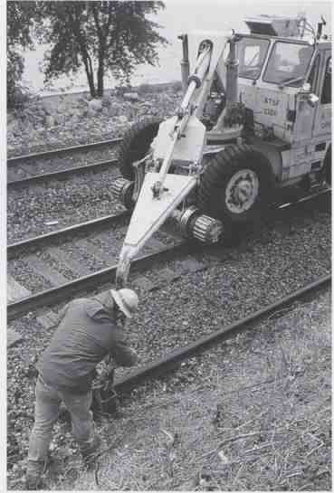
---ABOVE: A member of the BNSF steel gang working at Pepin, Wisconsin, attaches
a roller transport device to a section of welded rail. The specially equipped
Pettibone crane will transfer the rail from the drainage ditch to the track
center in preparation for installation.
65a---The Pettibone crane is one of 20 maintenance machines working with the BNSF steel gang at Pepin in September 2000. The tie crane slides the section of welded rail from the side of the track to the track center. This section of rail is roughly 1,500 feet long and weighs about 140 pounds per yard.
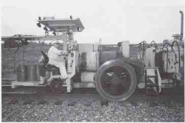
ABOVE---Rolling along at speeds of 1 to 2 miles per hour, Holley Engineering’s
spike reclaimer has large magnetic wheels on both sides to pick up spikes
and rail anchors along the right-of-way after they have been removed by
a spike puller.
A steel gang may use between 15 and 20 machines. While many of the machines have very specific functions, the men operating them are of ten trained to work with different types of machinery. This versatility and cross-training offers several advantages. It gives the crew members the chance to do different jobs, which keeps them from getting bored by doing the same fairly repetitive task day in and day out. It also gives each worker a clearer understanding of what the gang as a whole is doing. If every person on the gang knows what everyone else is supposed to do, it makes their working together as a team more productive and efficient. The flexibility to assign crew members to different machines allows the gang to be easily split up to take on smaller jobs, and it alleviates potential scheduling problems if someone in the gang is unable to work.
A Job for a BNSF Steel Gang
In September 2000, a Burlington Northern Santa Fe (BNSF) steel gang was given two repair jobs on the same stretch of the No. I track (west bound mainline) a few miles east of Pepin, Wisconsin. The track is the former Chicago, Burlington & Quincy mainline along the Mississippi River, connecting Chicago and the Twin Cities. This line was once the raceway of Burlington’s famous streamlined Zephyrs. Today it is a key component of BNSF’s principal Chicago-Pacific Northwest Corridor. While this section of track no longer handles passenger service, it is a busy freight line, accommodating up to 50 freight trains a day. To move this number of trains, most of the line between Savanna, Illinois, and Minneapolis is equipped with double track and directional signaling. When maintenance is performed, one track is taken out of service, and all traffic uses the remaining track. The dispatcher, who is located in a large control center in Fort Worth, Texas, has to “fleet” trains through the work area, using crossovers on either side to get trains from one track to the other. Although the one track remains open to traffic, trains must communicate with the official overseeing the track maintenance before proceeding through the work zone once they receive permission, the trains are allowed to proceed at reduced speed. Since the gang is working with loud machinery and is focused on the as signed task, the workers may not see a train sneaking up on them on the opposing track. Lookouts are stationed to sound air horns when a train is in sight.
This particular steel gang was equipped with an arsenal of about 20 different machines, arranged in the order in which they would be needed. The gang set out to work on the two jobs simultaneously. One job was to replace a length of continuous welded rail (CWR) near the village of Pepin; the other was a “gauging job,” which required re-gauging a section of rail on an S curve a few miles west (geographically northwest) of town. Since the two jobs involved similar work and were very close to one another, they could be undertaken simultaneously, with machinery going from one to the next.
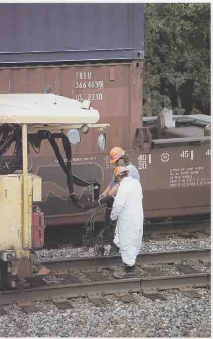
---ABOVE: Following the spike reclaimer, a machine fills the old spike holes
with an epoxy chemical compound to prevent decay in the holes, and to give
the new spikes a solid hold when they are inserted.
In anticipation of the rail replacement, a BNSF rail train laid down a section of CWR in the drainage ditch on the north side of the No. I track (westbound mainline). This was an adequate place to store the rail out of the way until it was ready to be installed, but the rail had to be properly positioned between the tracks before installation. The rail also needed to be dragged to precisely the right spot along the line. A 1,500-foot-long section of CWR is extremely heavy and can only be moved by machinery. The job of moving the rail was left to a former Santa Fe Pettibone Hyrail crane, equipped with a specialized rotating boom, and fitted with a roller attachment for moving rail. The Pettibone set up at the east end of the rail segment. A man on the ground assisted the Pettibone operator with fitting the roller attachment to the rail. Once it was in place, the Pettibone lifted the rail out of the ditch and swung it over to the center of the track, It did this by leveraging one end of the rail in place, and as the crane ran down the track it slid the rail over from the ditch to the track center as it went. After placing the new rail between the two outer rails, the Pettibone dragged it into position. The rest of the job was to be completed with machines that were working on the gauging project.
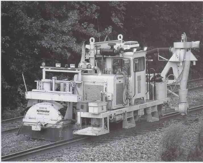
---ABOVE: The dual-purpose Kershaw Kribber-Adzer cleans excess ballast around
the ties to facilitate rail laying, and reprofiles a precision tie plate
seat on the tie. The machine is supported by rail on one side and by Caterpillar
treads on the other.
Further down the line, at the second site, the gauging job was already under way. Here the rail sits in the middle of the S curve. Heavy wear had broadened the gauge of the track slightly through the curve, and the rail needed to be completely re moved, and then put back, regauged, and refastened into place.
The entire entourage of track equipment working on the gauging project passed over the section of rail and set up at the far west end of the work site. Since the machines are lined up in the order of the job they do, and since they will proceed to the rail-replacement project as they complete their work on this job, the gang must start at the west end and work east otherwise, every machine will have to wait for the entire gauging job to be finished before it can move on to the rail replacement. A good maintenance planner has to think out every step of the maintenance process to get maximum use out of the gang.
The first machines to work the regauging job are an anchor remover and a spike puller, both built by Nordco. They proceed along the track clearing spikes and anchors from the rail and drop ping them on the ground. A Holley Engineering Model 58-10 Spike Reclaimer follows closely behind, picking up the metal parts that have been dumped. This clever machine alleviates the need for workers to pick up the discarded spikes and anchors by hand, and effectively allows one man to do the job of many. Built in April 1995, the model used on this job weighs 17,500 pounds. The Holley spike reclaimer employs two large electromagnetic wheels, one on each side of the tracks, to pick up spikes, anchors, bolts, and just about any other small bits of steel from along the ballast.
These steel parts are dumped into a V-shaped chute, from where they are deposited into a bin that sifts out dirt and debris from the steel. The steel is transferred to a constantly rotating cylinder that sorts the parts, which are then dropped by a conveyor into canisters on the back of the ma chine. A stash of empty canisters is stored on the front of the 58-10 Spike Reclaimer.

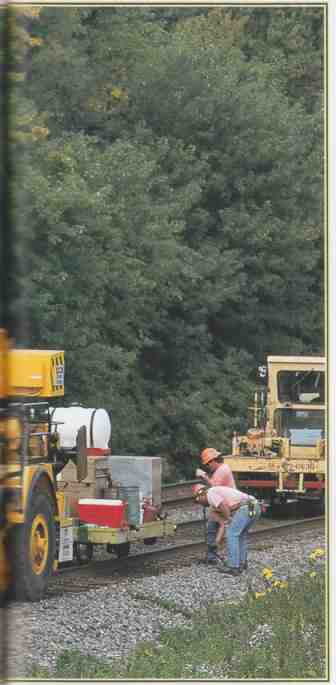
---ABOVE: A Grove crane re-lays and re-gauges a segment of welded rail.
This is precision work and the most important part of the gauging work.
The whole purpose of the job is to put the tracks back into gauge, which
may mean adjusting the rail by fractions of an inch.
Next in line is a machine that squirts an epoxy compound into the spike holes in the ties. Two men walking along behind the machine squirt the greenish colored epoxy compound into the holes using pressurized applicators on the end of hoses. This compound prevents decay and fills up the holes so that the new spikes grip properly when they are inserted into the old holes. Without this, the spikes might not hold well. Imagine pulling an old rusty nail out of a board and then putting a new nail back in the same hole. Unless something is done to reduce the size of the hole, the nail may not hold very well. Considering the thousands of pounds of pressure per square inch that will be placed on the spikes holding this rail in place, the new spikes must have a good hold, or there will be serious consequences. The epoxy does the trick.
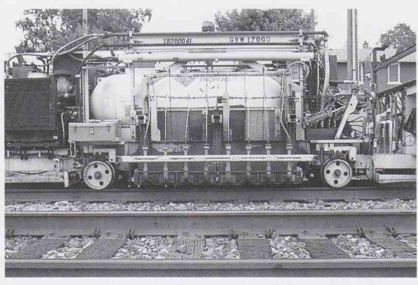
---69a A Teleweld rail warmer is a crucial piece of equipment when laying
continuous welded rail, as the rail must be heated to the proper temperature
before installation. Rows of propane heaters on the machine heat the rail
after it has been laid down and gauged, but before it is anchored in place.
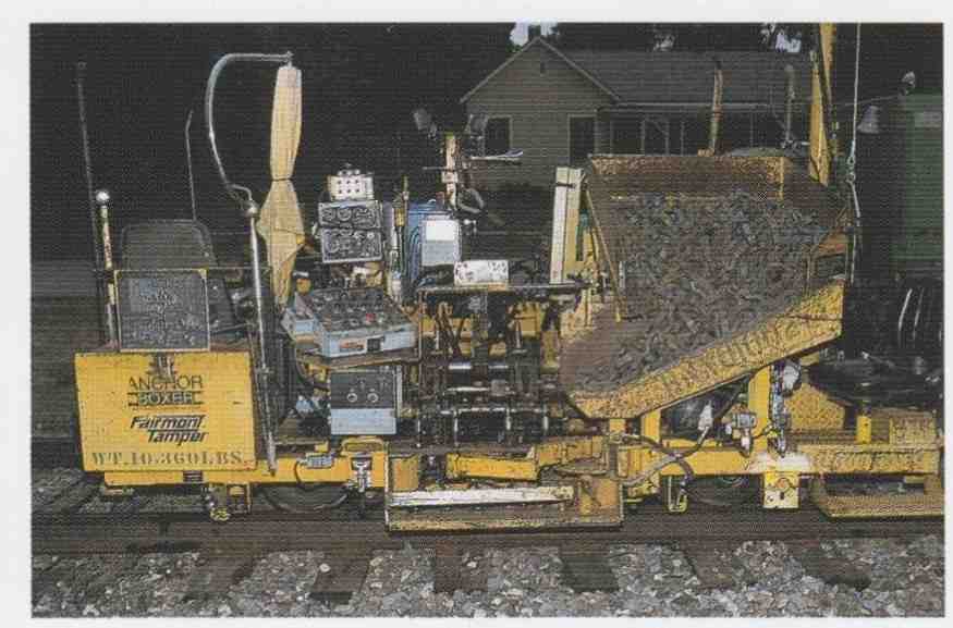
---ABOVE This Fairmont Tamper Anchor-Boxer is used to automatically clip
anchors to the rails. Rail anchors are especially important on welded rail
to keep it from sliding lengthwise along the tracks. The bin full of new
anchors is to the right of the operator controls.
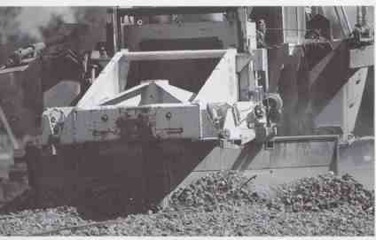
---ABOVE: Moving forward, the ballast regulator pushes and spreads the ballast
with its plow. The plow can also be used to draw ballast toward the track
center when the regulator runs in the opposite direction.
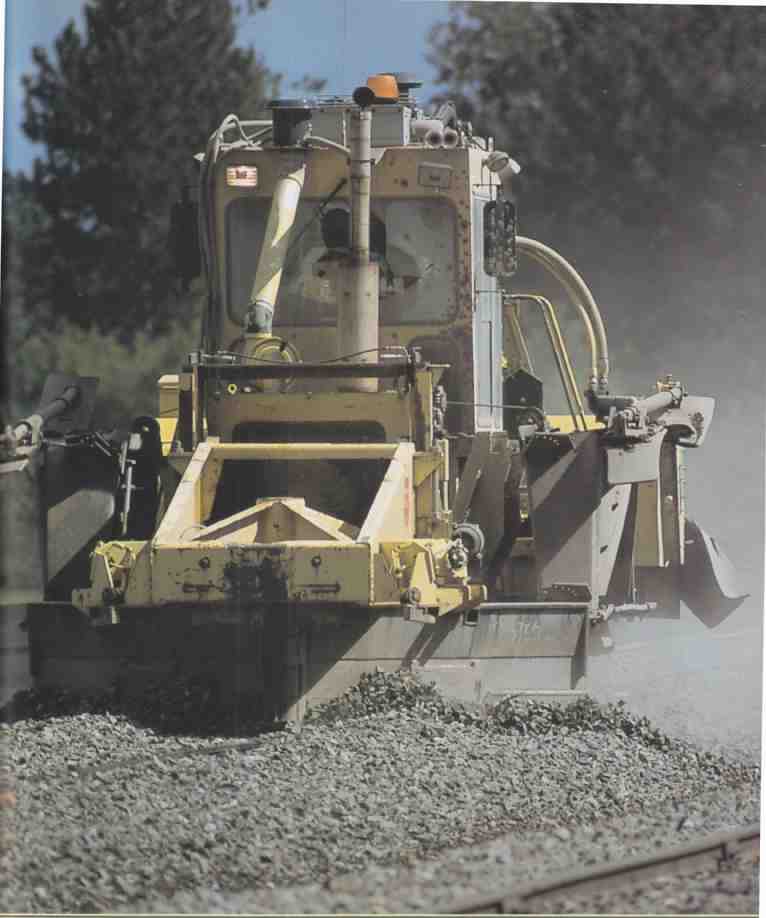
---ABOVE: A ballast regulator works the Wisconsin Central at Hawkins, Wisconsin.
Ballast regulators usually have three sets of tools for moving, sculpting,
and manicuring ballast: the plows, the ballast box, and the rotary broom.
The rail is now ready to be re-gauged. It is cut manually with a high-speed rotary saw. Another Pettibone tractor, this one running with its rubber tires on the ballast, lifts the rail off the tie plates and places it on the ties at the center of the track. Workers then walk along and manually lift the tie plates off the ties with rods and lay them in the ballast. These tie plates will be reused to seat the rail. Next along is a self-propelled cribber-adzer that is supported by a set of steel wheels on one side, which ride on the rail that is still intact, and on the other by Caterpillar treads. As the machine goes along, the operator brushes away excess ballast from the crib between the ties, and then using a computer-controlled adzer, cuts a precision tie plate seat on the top of the tie to ensure the re gauged rail sits properly.
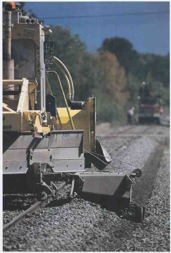
---ABOVE: The ballast box sculpts the ballast, giving it the desired angle
for proper drainage.
A large Grove crane then lifts the rail and lays it back in place. The Grove operator has the one job in the steel gang that requires a specialist, and only a few men on the gang are trained to operate it. Aligning the rail must be done with precision accuracy, and this task takes a little more time than the rest of the procedures. Several men follow along putting tie plates under the rail as it is positioned. Getting the tie plates to seat properly beneath the rail often requires a few whacks with a sledgehammer. The rail segment is not reconnected at this time this procedure must wait until later.
Once the rail is seated, a spike driver comes along to fix the rail in place. This is just a preliminary spiking, and another spiker will follow later to add more spikes. A tamper then shores up the ballast, and it is followed by a Teleweld rail warmer. The rail warmer is a fairly large two-piece machine that carries a large propane tank. It has rows of heaters that raise the temperature of the rail before it is fixed in place. Rail warming is a crucial operation to avoid future problems caused by rail expansion. The rail is brought up to 95 degrees Fahrenheit, which is the designated installation temperature for a rail on this line. When the rail is at the proper temperature, remaining fasteners are attached, including more spikes and rail anchors. The anchors are laid by a pair of anchor applicators that operate in tandem with each other. Two machines are used so that the anchors are applied as quickly as possible since rail anchors are designed to keep the rail from sliding length wise along the ties, the rail must be anchored in place before it cools.
As each set of machines completes its task on the gauging job, it proceeds down the line to the rail replacement job, where most of the same steps are repeated, except a new rail is installed instead of regauging the old one. The entire procedure for both jobs is accomplished relatively quickly. This gang is highly experienced so the work moves along at a steady pace with few difficulties or interruptions. All the while the gang is working, BNSF is rolling mile-long freight trains by.
Ballast Regulators
The ballast regulator is a common but versatile piece of modern railway maintenance equipment. While many track maintenance machines are limited to specifically defined tasks, the ballast regulator, like the Jordan Spreader, is an adaptable machine. It is designed to move and sculpt ballast, but it can be used for ditch digging, brush removal, plowing snow, and assisting with laying cable. A basic ballast regulator is controlled by a single operator, who drives the machine and oversees its operation. Most ballast regulators have three primary tools for working with ballast: plow blades that can be lowered over the tracks adjustable ballast boxes on either side of the machine and a rotating brush.
After rail and tie maintenance, ballast cleaning, undercutting, or any other work that disturbs, removes or alters the track and roadbed, a ballast train will lay down fresh ballast on the tracks. De pending on the nature of the work that had been completed and the type of ballast train used, ballast may be laid either to the side of the rails or between them. In order for ballast to be most effective, it needs to be packed around, between, and beneath the ties and sculpted to the desired profile. Heaps of ballast alongside the tracks or sitting atop the ties don’t help the condition of the track. A ballast regulator helps put ballast in its desired place. It often works as part of a surfacing gang that includes tamping equipment and other machines.
Regulators usually feature two angled, double-sided plow blades at the front, which can be used to move ballast backward or forward. The blades are angled to face away from the regulator. They are adjustable vertically and can work together or separately. Using the blades, the regulator can plow ballast off the track, drag ballast from the side of the track to the center, or even move loads of ballast from one side of the track to the other. Plowing is relatively straightforward. For ballast that is set on top of the ties between the rails and needs to be spread over the track, the operator simply lowers the blades to the desired height above the ties and drives forward over the ballast, spreading it across the tracks, filling in gaps, and evening it out. This is one of the simplest plow functions. A more complicated task involves moving ballast from one side of the rails to the other or to the track center. If a pile of ballast is set to the right of the rails and needs to be centered on the track, the operator drives forward past the ballast pile, stops, and lowers the plow blade on the right side, keeping the left-hand blade raised. He then reverses the regulator and drives back over the pile of ballast, drawing it toward the center of the track. Depending on the size of the pile, the type of stone, and the amount of ballast to be moved, this procedure may have to be repeated more than once. To move the same ballast to the left side of the track, another pass is required, essentially performing the opposite procedure: the regulator moves forward with the left-hand blade down and the right one raised, pushing the ballast to the left. Using this technique, a regulator operator can get ballast to where it is needed most and distribute it evenly all along the track.
The regulator operator sits in a central control cabin with windows on all sides to give him a good, clear view of the tracks and the action. Some regulators have two sets of controls (one for the right plow blades and one for the left) so that the operator can stay close to whichever set of blades he is working with, providing a better sense of control.
The ballast box assemblies on the sides of the regulator are adjustable. They can move laterally outward from the side of the machine, and pivot up and down to adjust the angle. As the regulator rolls along, the boxes are used to draw ballast on the side of the track closer to the centerline, and they sculpt and contour the ballast to the desired profile. A typical ballast profile on a lightweight single track line includes a 14-inch shoulder where the stone is level with the tops of the ties. Beyond the shoulder, the ballast should slope down at an angle that drops 1 inch for every 3 inches out from the track center. To achieve this profile, the regulator operator sets the ballast box to the desired extended position from the machine and angles it to the ground. He pulls the ballast into place by dragging the box along. This some times can be accomplished with just one well- planned pass over a given section of track, but several passes may be required, depending on the skill of the operator, the capabilities of the regulator, and the amount of ballast that needs to be moved. Ideally, modern regulators should be able to accomplish most jobs in a single pass, but in reality this is not always practical.
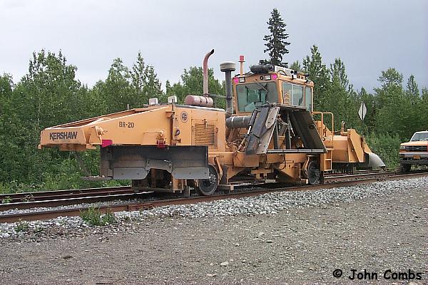
---ABOVE In this view, the regulator has its ballast box retracted and plows
lifted while the broom is deployed. The broom rotates quickly to sweep
excess ballast off the tops of the ties.
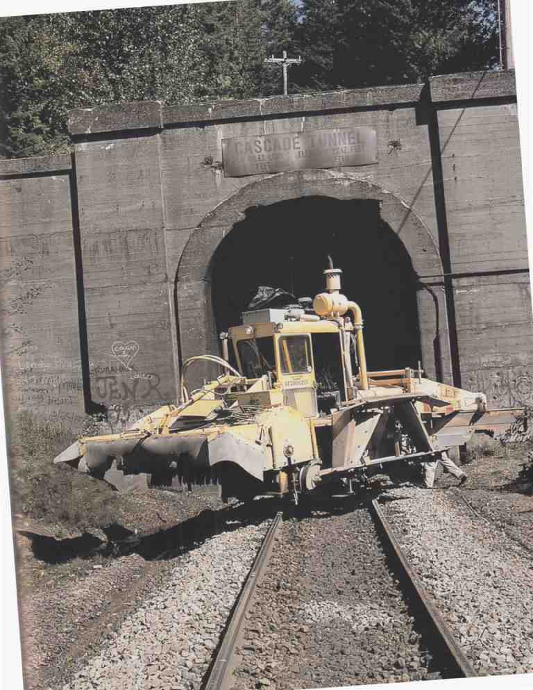
ABOVE: Many small track maintenance machines have built-in turntables that
allow a single operator to turn the machine around. This Burlington Northern
regulator is being turned in front of the Cascade Tunnel at Cascade Summit,
Washington.
After ballast has been moved, spread, and contoured using the plow and the ballast boxes, piles of stone are left on top of the ties. In order to clean off the ties and finish the job properly, the regulator is equipped with a spinning broom to remove stray stones and debris. The broom is composed of a rotating bar with multiple sets of five or six spokes radiating from it. One common type of regulator has 19 sets of spokes, five sets on the outside of each rail and nine in between. The spokes wear down rapidly, and they are usually made from an easily replaceable material such as used air-brake hoses. There is always a plentiful supply of these around a railroad, which makes them ideal spoke material. The hoses may be filled with wire cables to make them more effective in moving debris off the tracks. The broom spins rapidly as the regulator rolls along, kicking stones and debris off the ties, making for a clean, nicely manicured right-of-way. Rubber flaps are set up around the broom to keep rocks from escaping the regulator. Often a few stray ones will get loose, flying 20 to 30 feet away, so it isn’t safe to stand close to a working regulator. By the nature of the work it does, a ballast regulator stirs up a lot of dust. A machine plowing a pile of ballast will appear as a miniature dust storm raging along the tracks. Because of this, the best time for a regulator to do its work is when it is raining or when the ground is still wet from rain.
A ballast regulator at work is an amazing sight, but it is equally amazing to see a nice freshly regulated section of track. Before the ballast regulator arrives, track has a remarkably unkempt appearance. There are piles of stones heaped left, right, and center. The ends of the ties are obscured by ballast, and rocks are sitting all over the tops of the ties. After the ballast regulator makes its passes over the track, plowing, sculpting, and sweeping the stones, the right-of-way has a finished, polished appearance that exemplifies good-looking track.
Several different manufacturers produce ballast regulators, including Knox Kershaw of Montgomery, Alabama Nordco, of Milwaukee, Wisconsin and Harsco Track Technologies. In 2001, Knox Kershaw offered three ballast regulator models: the KBR825, KBR850, and KBR900. As one might expect from the model numbers, the KBR825 is the smallest in this family of machines and the KBR900 is the largest. The KBR825 is intended to accomplish each of its basic functions in a single pass. It has a one-pass transfer plow designed to move ballast from one side of the track to the other. Its side-mounted ballast wings are 36 inches wide and controlled hydraulically from the cab. The broom is also hydraulically controlled, and it has an adjustable deflector to protect against flying rocks. This deflector can be positioned as the ballast regulator moves through complicated track arrangements. The machine is powered by a Cummins engine and is designed for a travel speed of 30 miles per hour when it is not working. The KBR850 is slightly larger, and it has greater ballast moving capabilities than the KBR825. Its wings reach up 13 feet, 6 inches from the track center. The KBR900 is Kershaw’s largest model. Its simple, durable construction is designed to achieve the work as safely and efficiently as possible. Among its special features is a tilting operator’s cab, which can be adjusted to give the machine operator the best possible view of the tracks. The plow wings are designed to snap off the machine if it strikes an obstruction while working. This is a safety feature similar to a collapsing steering wheel column in an automobile, intended to pre serve the safety of the operator. The bolt holding the wing in place is set up as the weakest point of the whole assembly. In this way the bolt breaks rather than the wing or more substantial parts of the regulator. If the wing snaps off, the operator can reinstall it right away, using a new bolt to hold it in place.
Nordco calls its ballast regulator the Ground Hog. By using a rear-mounted engine, the regulator affords the operator a clear, unobstructed forward view of the tracks. Its four-wheel, hydrostatic propulsion is designed for a travel speed of 35 miles per hour. Like the Kershaw regulators, the Ground Hog is designed for single-pass operations, thus saving time by reducing the need for driving back and forth over the same section of track. The Ground Hog’s wings reach 14 feet from the track centers.
In 1986, the Tamper Corporation, one of Harsco’s predecessors, introduced its C-series line of modular track maintenance equipment. The C-series line was aimed at standardizing the use of basic components employed by different types of machines. (This standardization practice is nothing new to railroading the Pennsylvania Railroad began standardizing its locomotive de signs back in the 1860s.) Tamper standardized its designs to help reduce the cost of machine production and maintenance in order to counter the increased costs of implementing advancing equipment technology, among other expenses. Tamper’s modular approach to construction reduced the time required to produce the machines, limited the number of parts it needed to stock, and simplified operator training. Tamper’s C154BR ballast regulator, for example, shared components with its cribbing machines and track tampers. The C154BR not only employed a modular design but also had a greater capacity than earlier machines, and its specifications were in tended to match the capacity of tampers in the C-Series. Since ballast regulators often work in tandem with tampers, it is important that they do their work at about the same rate so that one ma chine does not fall way behind the work of the other. Some 15 years after it was introduced, the C154BR regulator is still produced by Harsco.

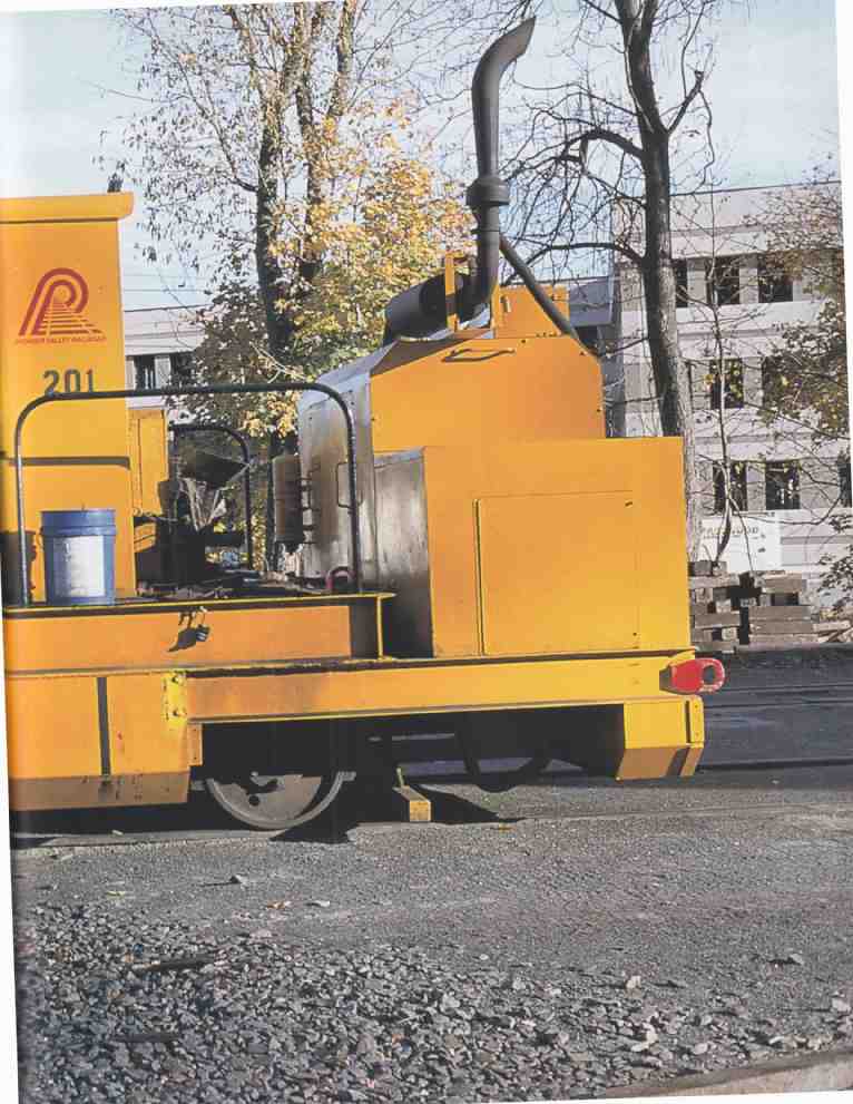
ABOVE: An example of a classic tamping machine, Pioneer Valley Railroad’s
tamper rests at the shop in Westfield, Massachusetts.
A modern C154BR regulator is 31 feet, 8 inches long a little more than 10 feet wide and 10 feet, 10 inches tall. The machine normally weighs about 56,000 pounds. It has a four-wheel-drive propulsion system powered by a 200-horsepower Cummins 6BTA 5.9 diesel engine. It is capable of a travel speed of 50 miles per hour. The front plow is 10 feet wide and is intended for single-pass ballast transferal. The hydraulic side wings extend 12 feet, 6 inches from the track center. The ballast boxes have a 1.75-cubic-yard capacity for moving stone. The hydraulic system is powered by a variable displacement pump that operates at 2,000 to 2,500 psi. The broom is mounted on the rear of the machine, a standard placement, and may be set to spin in either direction.
Some ballast regulators, such as the Plasser PBR-550, have a built-in ballast hopper, which allows the regulator to carry some of its own ballast. This feature is useful in situations in which the regulator requires additional ballast to do its work properly, but it is inconvenient for the railroad to send in a ballast train. The PBR-500 has a small hopper that carries 6 cubic yards of ballast.
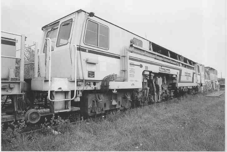
ABOVE: The large Plasser & Theurer production tamper is used by larnród
Eireann (Irish Rail). European railroads tend to use faster production
machines because they have less track time available for maintenance. Amtrak
uses similar tampers on its Northeast Corridor for the same reasons.
On a large surfacing gang, several ballast regulators may work together to dress a section of track. The number of ballast regulators required depends on the other types of equipment being used. Since the capacity and speed of different makes and models of maintenance machines varies considerably, it is important that machines are matched to one another for greatest efficiency, and to make the most of a given work window. For example, a high-capacity production tamper may be able to work at an average speed of 2 miles an hour, while a single ballast regulator might cover only one-quarter of that distance in the same amount of time. To keep up with the tamper, four or five ballast regulators may be as signed to work together on the same job. In the mid-1980s, Conrail’s typical surfacing gang had 55 people working a variety of different jobs, with more than 20 different machines, including six ballast regulators. The task assigned to each ballast regulator would vary depending on its position in the gang and the type of work being done. To minimize the amount of set-up time, a single regulator might spend the entire shift just plowing ballast, while another was given the sole task of brooming, even though each machine was fully capable of doing both tasks.
Most ballast regulators, and other types of small track maintenance machines, come equipped with a turntable that allows the machine to rotate and change direction. The turntable is simple to operate. It raises the machine off the wheels, spins it 180 degrees, and sets it back down again. This easy ability to change direction simplifies operations and adds to the ballast regulator’s versatility.
Tampers
Where there’s a ballast regulator, a track tamper is probably not too far behind. These two machines often work together in rehabilitating track. There are several different basic types of tampers, and dozens of different models. Tampers can perform three basic functions: track tamping, jacking (or surfacing), and lining, all of which are designed to improve the condition of the tracks. Tamping is the shoring up of the ballast below the ties to improve the support of the track. Jacking involves lifting and vertically aligning the track to even out bumps and other defects. Lining is the lateral alignment of the tracks. When these three features are properly combined and con trolled, the result is better-supported tracks that are straighter and more even than they were prior to tamping.
The mechanization of the tamping process has greatly speeded and improved this element of basic railway maintenance. Traditionally all the functions of a tamping machine were performed manually by a track gang. Tamping involved squeezing the ballast up below the ties, one tie at a time, by men with shovels and ballast rods and lots of elbow grease. Jacking was done with traditional track jacks, and lining was done by groups of men with large iron bars. Measuring the amount of jacking and lining was the responsibility of a track foreman, who eyed up the changes and issued verbal instructions to his crew. The whole process was labor-intensive, imprecise, and slow. The first step toward mechanizing the tamping process came with the introduction of automatic hand tamping tools in the 1930s. Later track-based tamping machines revolutionized track maintenance. Today instead of large gangs of men with bars and shovels, tamping is achieved by sophisticated automated track machines.
How Mechanized Tamping Works
A tamping machine has four pairs of metal tamping tools, each of which does the work once accomplished by two men with a tamping bar. The tamping tools are rods with small paddles, specifically shaped for moving ballast effectively. Two pairs of tools bracket the rail on each side of the tie, working similar to a large set of chopsticks, or a pair of pliers. They are designed to push through the surface of the ballast to a designated point below the tie and then squeeze the ballast up under the tie. Several different things must occur at the right time and in the proper sequence for the automated tamping to be properly executed:
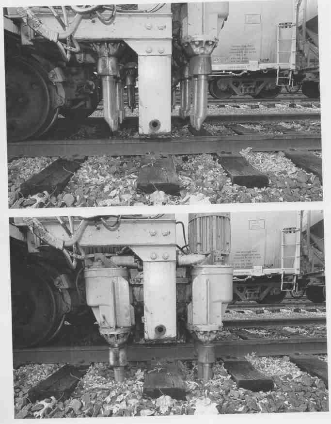
(TOP) These three close-up views demonstrate the sequence of the tamping
tools. In this first shot, the tamper tools are in the retracted position;
they are vibrating slightly. (ABOVE) The vibrating action helps liquefy
the ballast as the tools are thrust downward by the tamper operator.
To break the surface of the ballast, the tamping tools oscillate back and forth very quickly on the axis of the rods, usually at a rate of about 3,200 vibrations per minute. (To the naked eye it appears that the tamping tools are just shaking, and the subtle oscillation isn’t noticeable.) Four three- phase electric motors (one for each pair of tools) create the rapid oscillation, which has the effect of a miniature earthquake when the tools come in contact with the ballast. The oscillation effectively liquefies the ballast, providing the tools with an easy entry to do their work. As the tools are thrust into the ground, they contact a switch when they reach the proper depth (which must be set ac cording to the thickness of the ties). A signal is sent to large hydraulic cylinders that then squeeze the opposing sets of tools together, scrunching the ballast. The combination of the high-frequency oscillation and the scrunching is designed to cause the liquefied ballast to flow under the tie at the desire point. When the scrunching action is complete, the tools are automatically released and lifted back into their normal position above the tracks. The whole procedure takes just a few seconds and is known as the Tamp Cycle. The cycle itself has three steps: (1) downfeed, (2) squeeze in, and (3) squeeze out and upfeed. On older tamping machines, the operator had to manually actuate each of the steps; on modern machines, it is all done automatically.
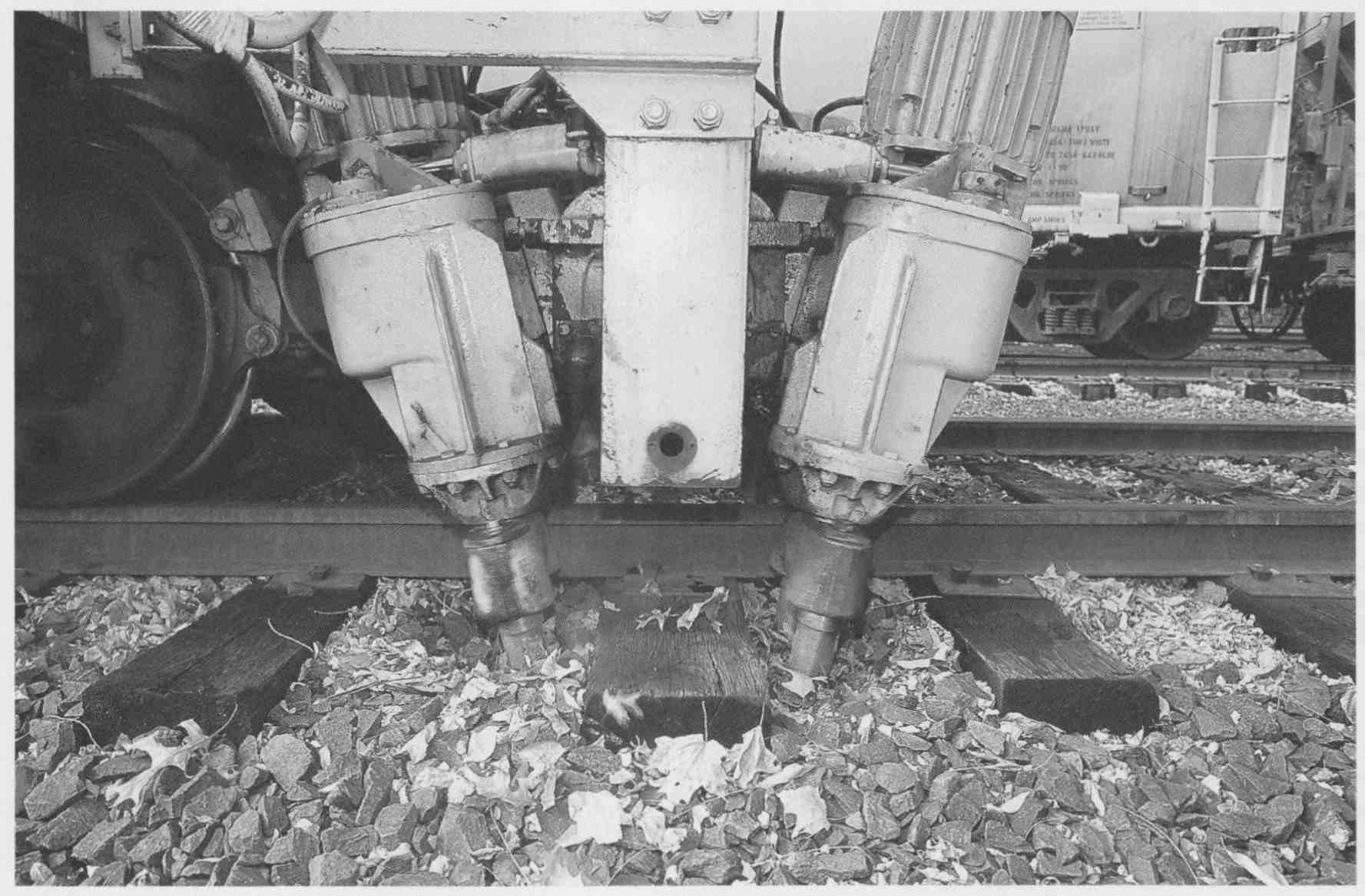
ABOVE: When the tools reach the proper depth, they are automatically squeezed
together, forcing ballast upward below the tie.
In order to get the best result from this tamping action, the tool has to be carefully set to reach the desired depth below the tie prior to squeezing. If the rods don’t go deep enough, the tie will get squeezed instead of the ballast, which dam ages the tie and fails to tamp the ballast in place. If the tools go too deep, the ballast flows over the tops of the paddles, resulting in a poor tamp that will not produce the desired support. For the best results, the top of the tamping tool paddles should stop about 1/4 to 1/2 inch below the bottom of the tie.
Track tamping theory has evolved from generations of experience. The most useful tamping action is obtained by uplifting the ballast only be low the areas near the rail, while the space between the rails should be left alone. The reasons for this are quite practical. The area below the rail requires the most support, and the passage of trains will tend to tamp the ballast below the ties. If ballast is mechanically tamped along the full length of the tie, the ballast below the center of the tie will eventually become compacted with the pas sage of trains. This is known as a center-bound tie. When a tie becomes center-bound, it no longer provides proper support below the rails and will rock back and forth under the weight of the train. In extreme situations this can actually cause the tie to break in the middle. The same type of problem can also be caused by over tamping a tie. Normally just a single tamp cycle by an automatic tamper will provide sufficient support to shore up the tracks.
Another factor in the amount and quality of the tamping is the amount of pressure the tools place on the ballast during the ‘squeeze in” part of the cycle. Under normal conditions, each pair of tools is set to exert a pressure of about 1,000 psi on the ballast. This results in much greater pressure actually being exerted on the tie, especially when all four sets of tools are tamping simultaneously (which is often the case when tamping track). In situations where ballast has become fouled and cemented through deterioration, greater squeezing pressure may be required. Under most circumstances, the pressure is kept below about 1,400 psi, except on some sophisticated modern computerized tampers.
Though tamping a section of damaged track can greatly improve its surface quality, tamping has some limitations, and it is not a panacea for poor track conditions. If the ballast has severely deteriorated, or if there is insufficient ballast, tamping may only prove minimally useful. Like wise, if rails are bent or ties are rotted and cracked, tamping may not help much at all. Tamping alone cannot cure the effects of serious track deterioration. For this reason, track tamping is often performed in conjunction with rail and tie renewal programs, and after fresh ballast has been applied and regulated.
Metal tamping tool paddles are rectangular in shape when new, designed for most efficient ballast adjustment, but even hardened steel has limited durability when repeatedly scraping against stone. The continual thrusting of the metal tools into the ballast causes the paddles to wear down. As the tools wear, efficiency gradually de creases to the point where the tools must be replaced. This point is normally about 30 percent paddle wear. If the tools are allowed to wear much more than this, the quality of the tamping begins to noticeably suffer.
Jacking and Lining
Because simply improving the ballast support without aligning the track will not improve the surface quality, modern mechanical production track tampers usually combine the basic tamping function with jacking and lining. A tamper that does jacking and lining must have a support system to allow the machine to lift up the tracks. This can be accomplished by incorporating a heavy frame superstructure around the jacking and tamping tools, which in effect makes the tamper a rolling bridge that supports the weight of the track structure during jacking. As a result, a production tamper—one that does both surfacing and lining work—is a much larger and more substantial piece of equipment than a basic tamping machine that performs only ballast tamping. On some Harsco tampers, such as the ES-TD, the support is accomplished with a torsion beam jacking system. On these machines, the large torsion beam transfers the track support from the rail to the beam.
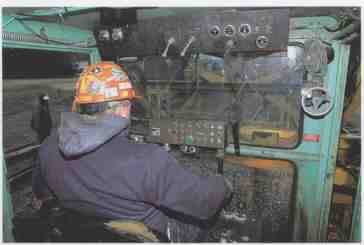
---ABOVE: Dick Gruber of Wisconsin & Southern tamps the yard at Janesville,
Wisconsin. This production tamper uses the Delta System for lining and
surfacing track.
Automatic jacking is achieved by a gripping device on the tamper that holds onto the rail and hydraulically lifts the track from above. Lining is accomplished by moving the rail laterally while it is being jacked. For the jacking and lining to have a lasting effect, it must be done at the same time as tamping, so that the track’s altered position is supported once the jack releases it. Most of these adjustments to the track structure require relatively small movements, yet they must be coordinated with precise accuracy for the track surface and alignment to be markedly improved.
Each tamper producer has developed its own distinctive system for coordinating automated jacking and lining functions. In the late 1950s Tamper developed its Delta System, which is still used to day by Harsco Track Technologies. The purpose of surfacing and lining is to remove irregularities in the track. To do this properly, the tamping ma chine needs to establish a point of reference from which to work. Tamper’s Delta System creates a reference point using a modulated red beam of light that is projected from a designated point in front of the machine, and is received by equipment behind the jacking and tamping equipment. The frequency of the light is modulated to minimize interference from outside light sources. Under most circumstances this system works as intended, although some tamper operators find that the machines can get confused at sunset, when high-intensity, low reddish light interferes with the projector. The Delta System uses basic triangulation principles of geometry to plot the amount of aligning needed in curves while maintaining a consistent reference point above the track.
The basic system for this procedure involves a frame that rolls in front of the tamper and holds the infrared projector. The distances between the projector and the tamper, and between the projector and the tracks remains constant. Typically the projector is set up 120 feet in front of the receiver. A signal i sent by the modulated red-light receiver to the motors that operate the jacks, which depend on the condition of the infrared beam transmitted by the projector. The jacks are equipped with a shadow board that interrupts the modulated red-light beam when the jacks have lifted the tracks to the desired height. When the beam is interrupted, the receiver sends a signal to stop lifting. Since all the other elements of the equation are constant, the result should be nicely aligned track. There are actually two sets of projectors, one for the horizontal plane and one for the vertical plane, which set the parameters for surfacing and lining respectively.
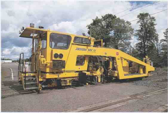
---ABOVE: Harsco’s Mark IV production tamper is designed for surfacing and
lining as well as basic tamping work. Its large truss frame is needed to
support the machine when it lifts the track during lining. This sophisticated
piece of modern equipment is used on many railroads in the United States.
The basic principles of this system are easiest to understand when tamping level tangent track; it is more complicated when working with curved track. This is where the triangulation principle comes in. The Delta System uses three-point co ordination. To accommodate curved track, the projector is linked to a sensor on the frame above the opposite rail. The sensor is designed to establish a reference plane above the tracks that reflects the angle of cross level in the track resulting from superelevation. (Superelevation is an angle in the plane of the tracks designed to compensate for the effects of centrifugal forces on railway cars as they roll through curves. In a super-elevated curve, the outside rail is slightly higher than the inside rail. When a tamper is working, it is extremely important that the desired superelevation is maintained.) There are two receivers at the back of the machine, one monitoring the surfacing beam, the other a cross level beam. Since the receiver is always at the level of the corrected track, the average inputs from the projector are used to maintain the desired superelevation and curvature. Prior to tamping, the tamper moves through the curve, measuring and plotting the average superelevation and curvature on a graph. Using a device called an Auto Graphliner, the tamper operator can make adjustments to the amount of superelevation and curvature that is put into the track by the jacking and lining. This device presents a clear picture to the operator that facilitates corrections to the curve geometry. Once corrections have been made to the plotted graph, the tamper is then ready to start again over the same section of track, implementing the desired corrections while performing its surfacing and lining.
Switch Tampers
A variation on the basic tamper is the switch tamper, which is designed to do tamping on more complicated track arrangements, such as switches and crossings. The primary difference between switch tampers and ordinary tampers is that the operator can laterally adjust the position of the tamping tools, which is very important when working on switches. On ordinary tampers, the heads are fixed in place and cannot be moved laterally.
Smaller tampers working on typical American freight railroads often operate in pairs or groups. On a large surfacing gang, a switch tamper may work ahead of a pair of surfacing and lining tampers, with a chase tamper following behind. While the tampers are performing similar actions, each one is doing a different job. On a smaller gang, there may just be two tampers. The lead machine takes care of the more complicated surfacing and lining functions, but only works every second tie. The chase tamper that follows is a basic tamper that shores up the al ternate ties that the lead tamper missed.
Models of Tamping Machines
Harsco’s Mark IV tamper is a typical machine used by many American railroads. As a standard feature it incorporates the old Tamper Delta System with a modern computer control system that is simple and easy to use. The computer regulates the machine during its various functions, and also measures, records, and analyzes the condition of the track in preparation for lining curves. It can also be equipped with a laser alignment system in place of the Delta System. The Mark IV is 39.6 feet long, 10.5 feet wide, and 10.5 feet tall. It weighs about 60,000 pounds. Among its features is a variable wheelbase that is 317 inches to 360 inches long. This allows for adjustments to improve the stability of the ties that have already been tamped by keeping the rear axle of the tamper close to the tamping heads. It also improves the machine’s lifting ability when working on complicated track arrangements. The tamper uses a strong boxed-beam steel frame construction, a trunnion-mounted front-axle suspension system and a fixed rear axle. It is equipped with 16 tamping tools, arranged in the standard pattern of eight opposing pairs. Its hydraulic oscillating vibrators are designed to work at 3,000 vibrations per minute, with a displacement of 3/8 inch. A Cummins 6CTA 8.3 turbocharged diesel engine provides power. The Mark IV has four-wheel-drive propulsion and has a travel speed of 35 miles per hour.
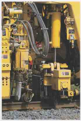
ABOVE: The Mark IV tamper lines and surfaces track by using a clamp that
attaches to the rails and lifts the tracks slightly while simultaneously
tamping the ballast below the ties.
Harsco’s Mark VI, Model 6700 is a typical production and switch tamper. It shares many of the same features as the Mark IV. Among its features are laterally adjustable tamping tools that will reach across the width of any normal switch or crossing. Like the Mark IV, the Mark VI is a truss-suspended machine with 16 tamping tools. It is designed to tamp at a rate of 1/2 mile per hour, and has a 45-mile-per-hour travel speed. It can work on tracks as steep as a 6.5 percent incline (that is, a climb of 6 1/2 feet for every 100 traveled), which is much steeper than any mainline American railroad, although some transit lines may have short ramps that approach that amount of gradient. The tamper is 43 feet, 6 inches long and has a fixed 30-foot wheelbase. It weighs 5 tons more than the Mark IV. Its jacking system can grab either the base or the top of the rail.
Plasser-American’s model 09-32 Unimat 4S is a massive switch and production tamper intended for complicated tamping jobs at interlockings and junctions, as well as rapid tamping on mainline tangents. The tamper measures 94 feet, 7 inches long; 9 feet, 9 inches wide; and 13 feet, 5 inches tall. It weighs 273,000 pounds. It has a 442- horsepower engine and is designed for a travel speed of 50 miles per hour. It has the ability to lift tracks at three points simultaneously and tamp four rails at the same time. This type of complex production tamper is popular in Europe, where multiple-track mainlines and heavy passenger traffic are the norm. It is also the type of machine used by Amtrak along the Northeast Corridor, where the high volume of traffic man dates frequent maintenance, but where work windows are relatively short to avoid interfering with passenger schedules.
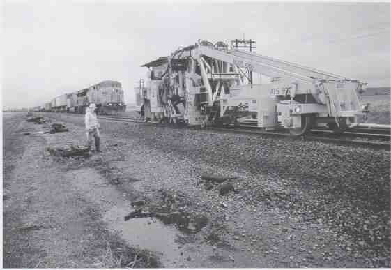
ABOVE: A Harsco Mark VI Model 6700 tamper works the Union Pacific mainline
in Nebraska on a rainy day in Spring 1999. The Mark VI is a modern production
tamper that uses a truss frame for support when lifting track.