Good drainage is essential to a solid track structure, and drainage is accomplished with proper ballasting and trackside ditches. High quality ballast is the key to good track structure and overall stability. Failure to properly maintain ballast will result in a gradual deterioration of the roadbed and subsequently the degradation of the tracks. If minor drainage problems and clogged ballast are left unchecked, they can lead to a serious maintenance problem and result in lower safe speeds and increase the likelihood of derailments.
One measure of a railroad company’s financial health is the condition of its tracks. A railroad with well-maintained, high-quality ballast shows that the company has allocated its resources toward proper maintenance and has a long-term outlook. By contrast, a railroad with poor ballast, low rail joints, and uneven track has neglected the very foundation of its track structure, and has cut corners for short-term gain. Excessively dirty, weedy, and unkempt ballast indicate more serious problems, both with the track structure and with the railroad company itself. When a railroad is tight for cash and looking to trim expenditures, cutting funds for track maintenance, particularly such projects as ballast renewal, is an easy way to save money in the short term. But ignoring fundamental maintenance is a gamble. In effect the company is mortgaging its future—and at a very high interest rate.
![]()
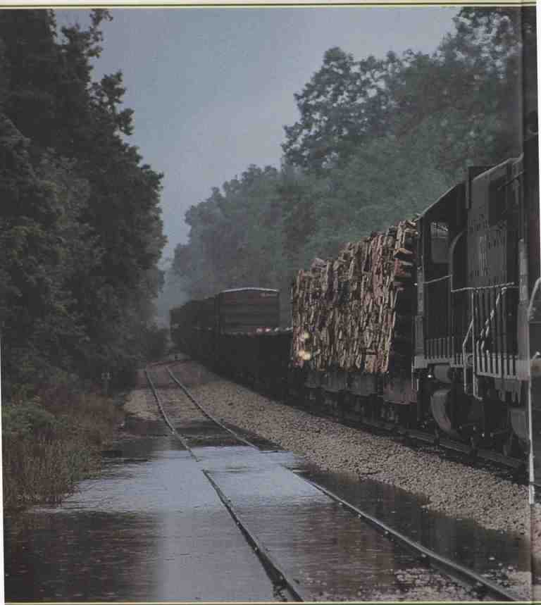
---ABOVE: Illinois Central’s Memphis to Grenada local carefully treads
through high water at Blanche, Mississippi, in April 1994. Proper ditching
and ballast maintenance is designed to draw water away from the track structure.
Flooding that brings water up to the level of the rail is extremely damaging
to the tracks.
Dirt Below the Surface
Fresh ballast is designed to drain water away from the center of the tracks into ditches along the right-of-way. The ditches then carry the water away from the roadbed. Most modern rail roads use crushed rock for ballast on the mainline. It is the most expensive conventional kind of ballast, but it has also proven to be the most effective. Crushed rock does a good job of holding the track in place, and it provides excellent drainage.
Crushed stone flexes beneath the weight of a passing train while remaining firm to hold the ties in place. Crushed stone is less prone to disintegration and cementing than other forms of ballast, yet all ballast gradually becomes fouled. Even stone ballast eventually breaks down and crumbles, becoming abraded as a result of passing rail way traffic and the cyclical freezing and thawing imposed by nature. Fine particles of abraded ballast, combined with natural dust and dirt, and debris that has fallen from passing trains, conspire to clog ballast, limiting its ability to drain water properly. In addition, fouling matter in the sub- ballast and sub-grade tend to work up through the good ballast, mix with water, and turn into mud. The mud then effectively seals off the crib between the ties and acts as a dam, preventing proper drainage and damaging the track.
Understanding how ballast clogs makes it easier to establish corrective measures to solve the problem and restore tracks to good condition. Ballast clogging is a vicious circle. As the ballast becomes clogged, its ability to drain properly deteriorates, and water gets trapped in the ballast, causing further damage that com pounds the situation. When the ballast becomes waterlogged, the up-and-down action of the wheels of a train passing on the track pumps water and debris from the sub-ballast, drawing it to the surface and further soiling the ballast. When severe pumping occurs, mud and water can be clearly seen around the ties and joints. This pumping is aggravated in track sections with poor rail joints, where there is greater movement caused by excessive pounding. As a result, tracks with traditional jointed rail are more prone to this type of ballast deterioration than modern welded rail, in which the joints are normally separated by as much as 1,500 feet, instead of each rail having a joint every 39 feet. The problem of clogged and cemented ballast is also more prone to occur on steeply graded lines, where locomotives are constantly laying down sand on the rails to gain traction. Heavily used railroads, such as heavy coal and ore lines that carry a huge amount of material that can fall on the tracks, suffer from more rapid ballast degradation than lines with cleaner traffic.
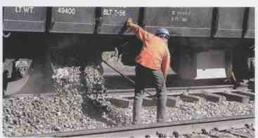
---ABOVE: A Montana Rail Link track worker manually dumps ballast along the
tracks at Muir, Montana, on September 21, 1994. Ballast cars are specially
designed to direct ballast on the tracks with chutes that can send the
Stone to either side of the rail. In this case ballast is directed outside
the rail.
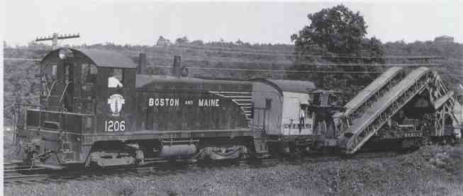
--- ABOVE: The Boston & Maine NW2 No. 1206 powers a traditional shoulder
ballast cleaner. The mechanized ballast cleaner is not a new concept; these
machines have been around for many years.
The depth of ballast and sub-ballast below it varies greatly from railroad to railroad, depending on the type of traffic hauled, the age of the route, and the type of ballast used. Traditional mainlines, particularly those in the eastern and midwestern United States, tend to have the deepest layer of ballast and sub-ballast, as a result of years of ballast renewal. One conventional method of track renew al was to dump fresh ballast across the tracks, and then jack the track—ties, rails, and all—through the layer of ballast and tamp it down. In this scenario, the old ballast often becomes sub-ballast. On some older lines, the combined layer of ballast and sub-ballast runs more than 3 feet deep below the ties. Normally tracks should not be lifted more than about 8 inches during ballast renewal if the tracks are lifted higher than that, there is high risk of uneven settling, a condition that may prove more troublesome than clogged ballast.
Ballast Cleaners and Undercutters
Repeatedly dumping ballast on tracks has its limitations. Every time ballast is added to the tracks, the tracks get a few inches higher. This begins to present problems at underpasses and other places with limited overhead clearance. Ballast cleaning has long provided a solution for difficulties with fouled ballast. In the days before mechanized track machinery, ballast cleaning, like nearly all railroad maintenance, was accomplished by hand. Men with picks and shovels re moved soiled ballast and ran it through a sieve to shake out foreign matter. The ballast was then re placed manually. It has been a long time since American railroads relied on this primitive method of ballast cleansing. Since the steam era, machines have been designed to do this job faster and more effectively than it could be done by hand. Shoulder ballast cleaners are one such tool. These machines are designed to clean the ballast along the edge of the tracks. Though this method cleans only 30 to 40 percent of the ballast on the right-of-way and leaves the majority of the bal last between the ties untouched, the theory be hind it is that if the shoulder is cleaned and pro filed properly, the muddy dams will be broken, allowing the natural drainage of the track to flush unwanted debris and silt from the cribbing area between the ties.
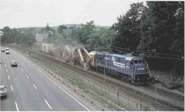
---ABOVE: Conrail’s C30-7A No. 6596 leads a Speno shoulder cleaner at Auburndale,
Massachusetts, on July 18, 1985, clearing the debris at the end of the
ties. Such debris causes damming in the cribbing between the ties. The
shoulder cleaner removes the dams to restore proper drainage, allowing
the ballast to function as it is intended.
A shoulder cleaning ballast machine rolls along on the tracks at a working speed of just I to 2 miles per hour. It excavates ballast on both sides of the track as close to the tie ends as it can with out the risk of damaging them. The dirty ballast is deposited on a set of large vibrating screens with in the machine. The screens serve the same function as the old sieves, separating out the ballast from unwanted debris. The cleaned ballast is re-deposited along the track, while the debris is sent by rotary conveyor into hoppers that are hauled along by the train, or it is thrown a safe distance from the tracks. Since dumping the debris back onto the right-of-way is not always feasible, a bal last cleaning train might tow several hoppers along behind it. The amount of work a ballast cleaner can do is limited by the capacity of its hopper train. When the hoppers are filled, the train must travel to a designated landfill to dump the debris before it can continue its ballast cleaning. The rate at which the hoppers are filled depends on the rate of ballast cleaning and how soiled the ballast has become.
A modern shoulder ballast cleaner manufactured by Loram excavates between 2 and 2.5 feet of ballast beyond the tie ends on either side of the track, and reaches down 6 inches below the tie level. It also employs a scarifier to the tie ends to remove the silt and mud that has dammed the crib area and impeded drainage. Lo ram machines have built-in ballast regulators and brooms that contour and trim the ballast to the correct profile after it has been cleaned and re deposited along the sides of the track.
![]()
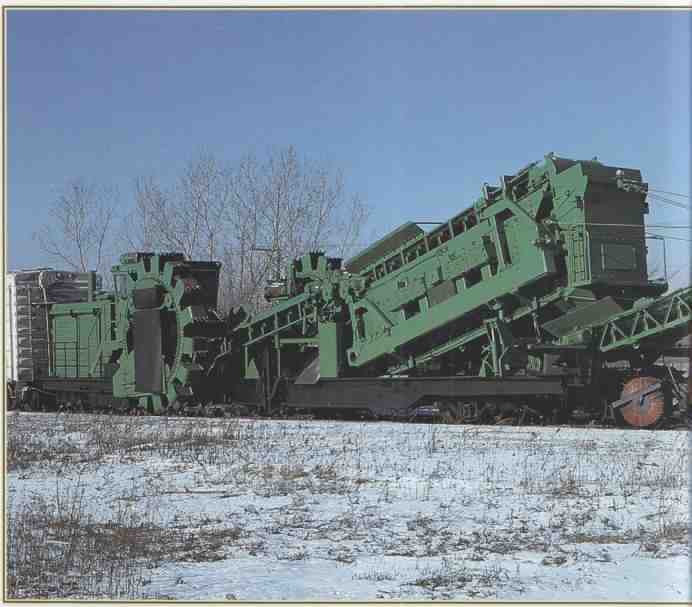
---ABOVE This shoulder cleaner uses its large cutting wheels to remove
ballast along the side of the track. The material is then sifted to remove
sand, dirt, and foreign matter that causes fouling, and the ballast is
dumped back on the tracks, while the fouling matter is thrown to the side
or dumped into hopper cars towed along with the cleaner.
While shoulder ballast cleaning can be the most cost-effective way to restore proper drainage to a line suffering from clogged and contaminated ballast, it has its limitations. Ballast can only be cleaned so many times before it breaks down to the point where it is no longer effective. In addition, ballast that has deteriorated to the point that it is completely fouled cannot be effectively corrected by shoulder cleaning. In these cases it may be necessary to remove the ballast with undercut ting machinery and then completely replace it. Undercutting is also used where insufficient vertical clearance prohibits the raising of tracks during ballast renewal, such as on lines that pass through long tunnels or through urban areas with numerous overhead bridges. In these instances, under cutting may be the only effective way to restore proper drainage.
Some undercutting machines use a continuous chain placed below the tracks to scoop away ballast and debris. Others use a large rotary wheel to dig a lineside trench and a bar placed below the tracks to remove fouled ballast. As with ballast cleaners, an undercutter can deposit the material into hoppers with a conveyer or distribute it well away from the tracks to keep the old ballast from interfering with drainage. Since an undercutter does not return any material to the roadbed, it tends to fill hoppers more quickly than ballast cleaners. While a ballast cleaner just deposits fouling material in the hoppers, an undercutter deposits everything it scoops up. Modern ballast machines sometimes combine undercutting and ballast cleaning functions.
Harsco Track Technologies’ Trac-Gopher (Model GO-4S) is a 100,000-pound undercutter designed for mainline and switch/highway-crossing work. Using a 12-foot, 7-inch trenching wheel, it is designed to cut a 20-inch-wide trench up to 34 inches deep alongside the track. The trenching wheel can be laterally adjusted, allowing the trench to be located anywhere from immediately adjacent to the ties to up to 9 feet from the center of the track. Once a preliminary trench is excavated, a 15- foot-long, 6-inch-deep cutting bar is placed below the tracks to remove ballast from below the ties. The bar is adjustable to allow undercutting from 6.5 inches to 2 feet, 3 inches deep. The undercutter is powered by an eight-cylinder General Motors diesel engine that runs at 1,200 rpm, generating 364 horsepower. The undercutter runs on four 30- inch wheels and has 15,000 pounds tractive effort, enough to tow up to four 100-ton loaded ballast cars on level tangent track. Undercutting spoil is transferred to a conveyor that can throw it as much as 45 feet from the track, or deposit it in ballast cars. While the Trac-Gopher has a travel speed of up to 25 miles per hour when it isn’t undercutting, its working speed is just 2 to 10 feet per minute. At this speed, it can undercut a maximum of 600 feet of track per hour. The machine itself is 15 feet tall, 10 feet, 6 inches wide; and 40 feet long. Unlike traditional undercutters that had minimalist wire-frame cabs, the Trac-Gopher has a comfortable, completely enclosed operator’s cab. It is relatively spacious inside, and is insulated, pressurized, and equipped with a heater and an optional air conditioner.
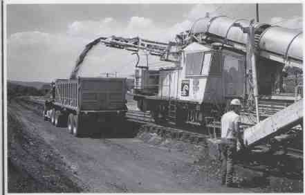
---ABOVE: Conrail’s Dirt Devil undercutter chums away at Milepost 81 along
the Boston & Albany. In the 1980s, many lines used specialized machines
such as this one to increase their mainline clearances in order to accommodate
taller trains.
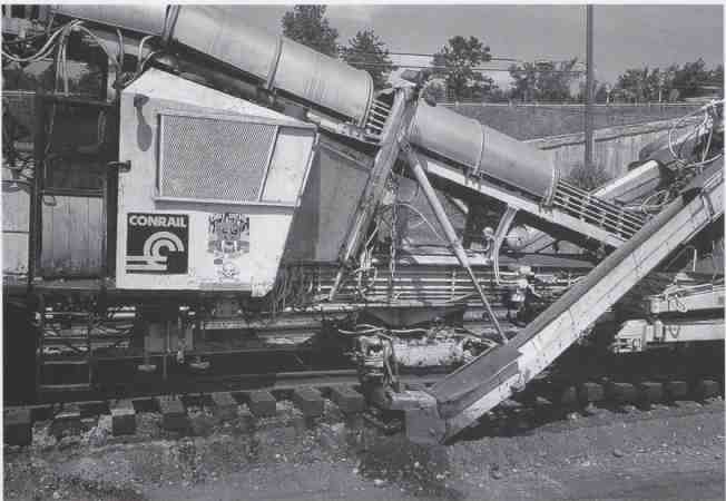
---ABOVE: The undercutter uses an excavating chain placed below the tracks
to remove ballast and soil from beneath the ties. As the machine moves
forward (to the left in the photo), the debris is dropped in a hopper (seen
on the right), which sends it away from the tracks via conveyor belt.
In addition to ballast renewal considerations, railroads may decide to undercut track as a way to increase clearances. In situations where it is physically difficult, prohibitively expensive, or politically impossible to raise vertical clearances, undercutting is an attractive alternative for improving clearances on the line. In the mid-1960s, the Pennsylvania Railroad chose to undercut portions of its Philadelphia-Harrisburg mainline to better accommodate tri-level autoracks. The line is electrified with overhead catenary, energized with 11,000-volt alternating current. Prior to its clearance improvement project, Pennsylvania Railroad experienced occasional difficulties with wires coming into contact with the tops of new automobiles on auto-carrying freight cars. (This was in the days before protected covered autoracks, and the cars simply ran out in the open.) One can just imagine the spark show when brand-new Chevys or Fords hit the wires! Undercutting was required where low overhead bridges forced the level of the wires too close to the tops of the cars.
In the mid-1980s, American railroads began to take advantage of deregulation, spurring the in creased operation of double-stack container trains. At the same time, concerns from automobile manufacturers about vandalism to new cars riding in open autoracks led to the development of tri-level covered autoracks. Since these new types of railroad cars were several feet taller than most conventional cars, many railroads undertook massive clearance improvement programs to accommodate them. Again, undercutting was often the preferred option.
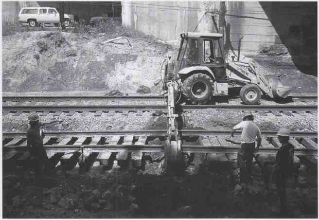
---ABOVE: Before the undercutter can get its cutting chain below track level,
a backhoe removes ballast, and the tracks are jacked up. Here at Milepost
81 on the Boston & Albany route, the tracks are being lowered about
1 foot to increase the vertical clearance and permit the operation of tri-level
covered autoracks and other tall cars.
Ballast Trains
Fresh ballast is often needed during track work to replace soiled ballast or to replenish existing ballast, or it is laid down in preparation for new or relocated track. Ballast is typically quarried on line and distributed around the railroad in specially assigned ballast trains. While railroads may designate old coal hoppers or ore jennies for the task of transporting ballast, often they utilize more specialized equipment. Air-actuated side- dump cars are used to distribute large quantities of ballast to the sides of the right-of-way. The Difco dump car is a common type of commercially produced air-actuated dump car. For general distribution, specialized ballast hoppers are employed to haul and dump the stone. Since ballast is extremely heavy, ballast hoppers tend to be lower, shorter, and more durable than hoppers used for coal. Ballast hoppers are also designed to distribute their load along the tracks, and simple coal chutes are not the most effective way of doing this. A good ballast hopper can easily control the amount and direction of ballast dumped, and directing the flow of ballast to either inside or outside the rails is an important function of the ballast trains. Traditionally, ballast was spread along the tracks very slowly, usually no faster than walking speed. As the ballast train crawled along, employees walked beside the train and distributed the ballast by opening and closing chutes as needed to regulate the flow.
Technology is catching up with convention al methods. In 2000, the Herzog Contracting Corporation, one of the leading lessors of ballast equipment, introduced a modern high-tech bal last delivery system known as the Programmed Linear Unloading System, or PLUS train. Where conventional ballast trains delivered ballast at less than 5 miles per hour, Herzog’s PLUS train can dump ballast with precision accuracy at speeds up to 20 miles per hour. This space-aged ballast train uses modern computer and Global Positioning System technology to do its job. A skilled Herzog technician rides ahead of the PLUS train with a railroad representative, ideally a road foreman or track maintenance supervisor, and takes detailed notes as to the desired location and quantity of ballast needed. This information, along with the location of bridges, switches and obstructions that may interfere with ballast distribution, is logged on-site into a laptop computer. It is later downloaded to a computer on board the train, which uses the in formation when applying ballast. The hopper door controls are extremely sensitive, and de signed to carefully regulate the flow of ballast to the track. The computer on board the train takes the speed of the train into account when delivering the ballast, adjusting the door openings to compensate for the speed. If the train is moving faster, ballast needs to be dumped at a greater rate than if the train is moving slowly. This system minimizes problems caused when a ballast train slows abruptly during ballast spreading. The ballast doors on the PLUS train are larger, and open and close up to five times faster than on more conventional equipment, which permits the train to dump its load much more quickly. A PLUS train of 50 100-ton hoppers can deploy its entire load in less than an hour. Such a time saving is a great advantage to modern railroads with limited time windows available for track work. Since the entire train is automated and the ballast sites have been predetermined, it is unnecessary for railroad personnel to be on the ground, offering an additional saving for the railroad. Like other modern track-monitoring equipment, the PLUS train’s survey system records the information and holds it for future ballasting needs. This allows a railroad to determine if a particular stretch of track is using an excessive amount of ballast over time, and appropriate remedial action can be taken. Herzog hopes that its new train will win favor with American railroads by its increased productivity and cost savings.
Ditch Diggers
Directing water away from the track is a routine yet extremely vital aspect of a railroad’s maintenance program. Standing water undermines track stability, and as a result, drainage ditches are a standard part of railroad construction.
Traditional ditching methods were time-consuming, labor-intensive, and expensive. The work required large gangs of men along with steam shovels and other equipment. As railroad technology progressed, ditching moved from conventional manual methods to mechanization. One of the first mechanized ditching tools was the Jordan Spreader, discussed in detail later in the section. Though the Jordan was an excellent tool in its day, and some lines still use them, new more advanced machines have superseded the Jordan Spreader as the ditching tool of choice. Because today’s railroads demand maximum track utilization, making maintenance windows precious commodities, specialized ditching machines have been developed that operate much faster, more cheaply, and more accurately than more conventional machines.
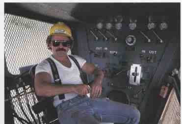
---ABOVE: The operator amenities in Conrail’s Dirt Devil undercutter are minimal,
but the controls are relatively straightforward.
The primary objective of a ditch digger is to move away earth and water while profiling the land to create a drainage ditch. The ditch is designed to lower the water table around the tracks by drawing water away from the roadbed. To make the best use of a modern ditch digger, facilitate fast ditch digging, and minimize its time on the mainline, rail roads will prepare a site in advance and clear away debris. Anything that might damage, clog, or delay ditch digging machines is removed by workers and machines on the ground. This includes, for ex ample, old crossties, fragments of broken rail, large rocks, and brush.
=====
Conrail Ballast Express
Some railroads paint ballast fleets distinctively to distinguish them from revenue service cars. Union Pacific’s ballast cars are treated with a forest green livery, Amtrak’s are a brilliant safety orange, and Conrail’s were a light gray that almost matched the color of the stone they carried. While many railroads assigned any surplus motive power to ballast service, a few have designated locomotive fleets for work or ballast trains. Conrail obtained much of its ballast from a quarry in West Springfield, Massachusetts, along the old Boston & Albany route. Ballast quarrying is strictly seasonal business in New England because of the cold and sometimes snowy winters, so most of Conrail’s ballast was delivered in the spring, summer, and early autumn. In season, a train or two of ballast would be loaded every day, and then hauled over Washington Mountain for distribution on the rest of Conrail’s system. This was an especially difficult pull, involving a winding 1.67 percent climb between Chester and Washington. Conrail locomotives would slow to a crawl trying to haul the ballast trains over the hill. While most trains made it without serious problems, all too often a heavy ballast train would stall a few miles west of Chester, Massachusetts, as it entered the reverse curves at Milepost 129.
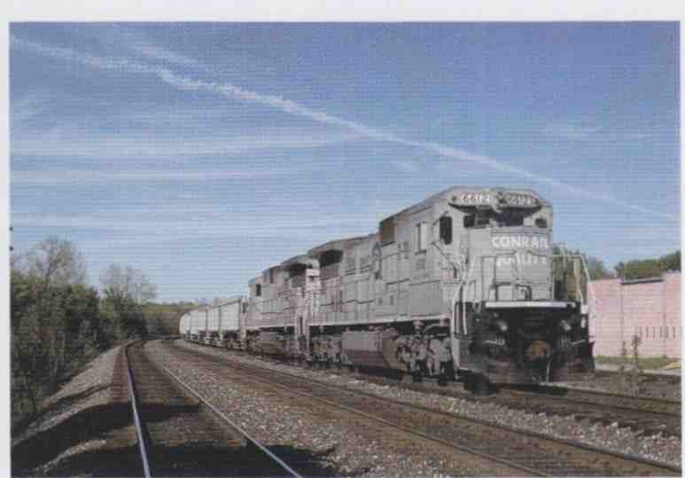
---ABOVE: A pair of Conrail’s unique General Electric C32-8s, in Ballast
Express paint, work on the former Pennsylvania Railroad at Latrobe, Pennsylvania.
The 10 Conrail C32-8s were the only examples of this type of locomotive.
Conrail reassigned the fleet to work train service in the late 1990s.
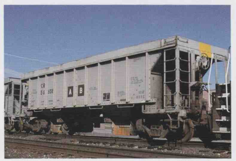
---ABOVE: This Conrail ballast hopper has remote-controlled ballast doors
that permit rapid spreading of ballast along the right-of-way. The car
can carry up to 200,000 pounds of stone. Notice how the chutes are aimed
to direct ballast to either side of the rail.
For many years, Conrail’s ballast trains warranted the same types of six-axle locomotives used by the other Conrail trains on the B&A. Toward the end of Conrail operations, before the railroad was divided by Norfolk Southern and CSX, Conrail reassigned its fleet of 10 General Electric C32-8s to Boston Line ballast service. These unique locomotives were delivered to Conrail in 1984 and spent much of their careers working on the Boston Line. The locomotives were unusual for several reasons: They were the only C32-8s ever built and they used a 12-cylinder FDL engine, instead of the far more common 16-cylinder FDL engine. Externally they had the Classic Dash 8 car body, with curving contoured cabs—a body style that was in production for only a few years. In the mid I 990s these locomotives were repainted from Conrail blue to a distinctive gray scheme and lettered for Ballast Express service. For several years they were regularly assigned to ballast work and hauled loaded stone trains all over the system. When there wasn’t ballast work for them, Conrail used them on other Boston Line services. CSX also assigned some locomotives in work train service, painting them a bright safety orange and assigning them to ballast trains and other maintenance-of-way duties.
=== ===
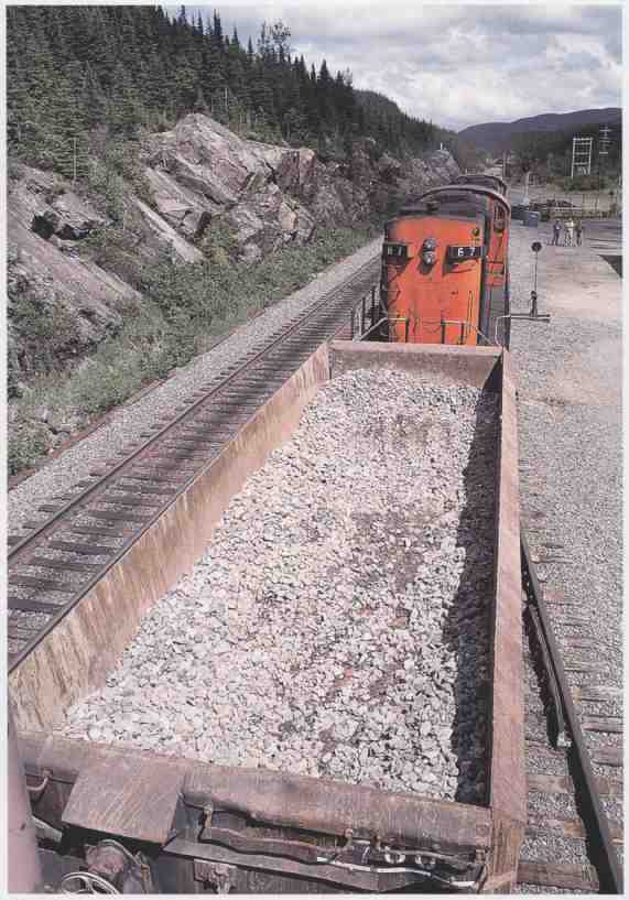
--- ABOVE: This work train on the Cartier Railway in northern Quebec offers
a good view of a dump car used to distribute ballast. It can dump to either
side of the track. Because of its isolated nature, the Cartier still does
most of its maintenance with traditional rail-based equipment.
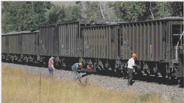
--- ABOVE: A trackman on the Montana Rail Link adjusts the traps on loaded
ballast cars in preparation for spreading the stone on the tracks.
Loram, the maintenance equipment contractor known for its undercutting and rail grinding services (see section 5), also offers one of the most modern mechanized ditching machines. This able machine is named after the badger, a mammal known for its rapid burrowing ability. A badger can dig a hole with its paws much faster than a man could with his hands; likewise, Loram’s Badger ditch digger is designed for greater speed and efficiency in digging trackside ditches. The Badger is a self-propelled machine that can attain a travel speed of 45 miles per hour, which gets it over the railroad fast when moving between work sites. It features two adjustable arms for digging. One carries a high-speed digging wheel to sculpt the ditch, and the other is a conveyor to remove earth and water from the digging site. The Badger can dig a ditch between 6 and 18 feet from the track center, and can cut down to 4 feet below the rail level. It can profile a ditch to most specifications required to improve track drainage. Many ditches can be dug with a single pass of the Badger, but some may require multiple passes, especially more complicated terraced ditches. The Badger works much faster than older machines, meaning more works gets done in less time. At its best, the Badger can move as much as 1,000 tons or 500 cubic yards of earth and water every hour. The conveyor can be aimed to deposit ditch waste up to 35 feet from the tracks, or into air-actuated side-dump cars carried along with the digging ma chine. The method of waste disposal depends on the area being ditched. Drainage problems often occur in deep rock cuts, and in such constraining environments, it is more convenient to use the dump cars for waste removal.
Unlike other elements of track geometry and roadbed design, ditch digging is a fairly inexact process. The theory behind ditch placement doesn’t always work the way the railroad hopes it will. A ditch may function adequately under normal circumstances, draining runoff away from the roadbed and keeping the right-of-way sufficiently dry, but be inadequate for more extreme conditions. For example, railroad ditches have to accommodate a lot more water during heavy rains than they do on normal days. If they fail, tracks can flood or wash out. Washouts are relatively rare these days, and accidents caused by washouts even rarer. They can still happen, however, so maintenance crews must be on their toes, keeping drainage systems up to par and ready for the big 10-year or 50-year flood. In assessing ditch capacity, routine drainage and extreme flooding need to be considered separately.
When planning ditches along its lines, a rail road needs to weigh the costs of ditching against the risk and impact of severe floods. In some cases, no amount of trackside ditching will help, and in these situations other alternatives must be considered. For example, railroad lines that cross the Sacramento River Delta and flood plain are built on trestles, rather than embankments, even though most of the time the area below the tracks is bone-dry. When the flood does come, the trestle is the only way to go.
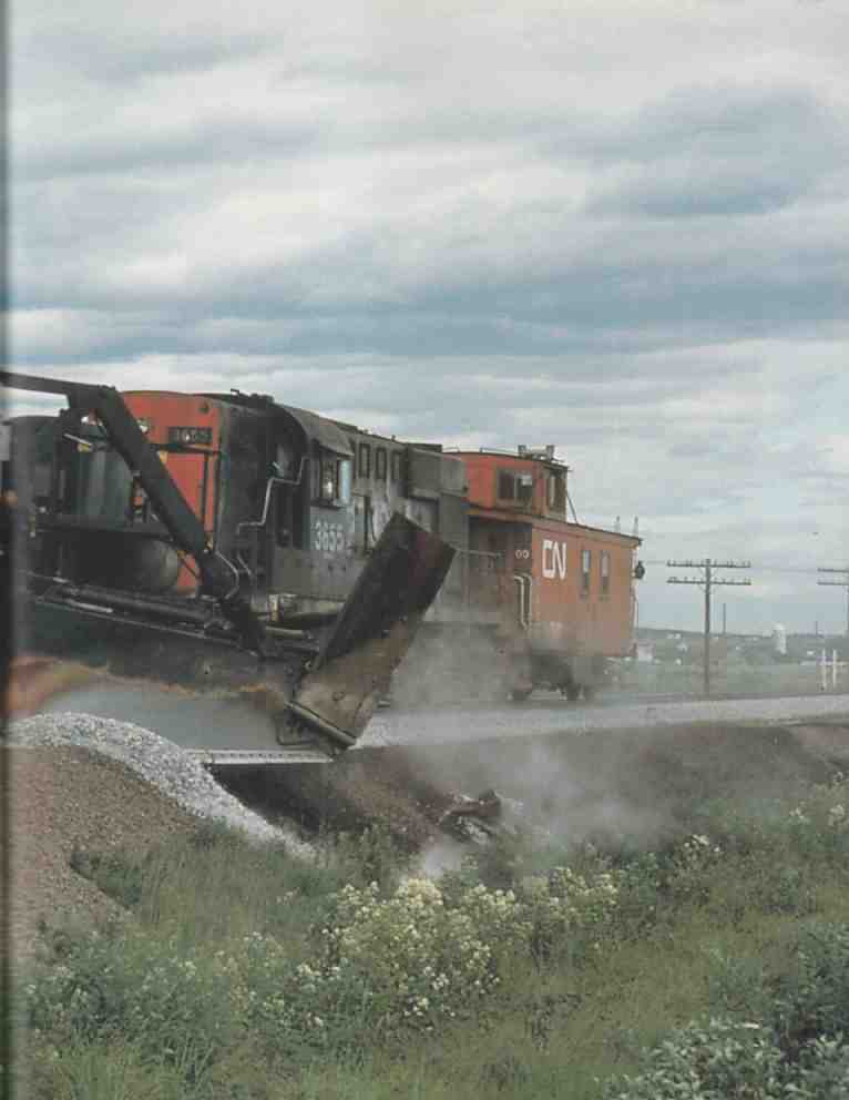
---ABOVE: On July 12, 1978, a Canadian National Jordan Spreader shapes
ballast as it is shoved along. The Jordan’s adjustable wing was designed
for this type of contouring work. Versatility was one of the Jordan’s great
attributes; this one machine could be fitted with more than a dozen different
attachments.
Jordan Spreaders
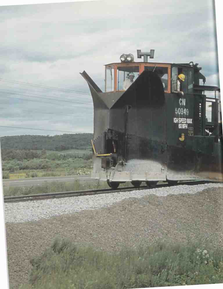
It is difficult to find a piece of equipment that is as universal and as useful for railroad maintenance as the Jordan Spreader. It is one of the oldest types of maintenance machines employed by modern railroads, and at one time it was among the most common. While it has largely been sup planted by more modern, specialized maintenance equipment, the traditional Jordan Spreader can still be found on many railroad lines. The Jordan can work as a ditching machine, a ballast regulator, and a heavy snowplow. It combines all these tools in one rugged, adaptable, low-tech piece of equipment. The Jordan is one of the last relics of the steam era still found on American railroads.
The Jordan Spreader is named for its inventor, Oswald F. Jordan, a one-time roadmaster for New York Central’s Canada Southern Lines. In 1905, he left the railroad, and applied his years of experience to developing, building, and marketing a track maintenance tool that was superior to anything else available at the time. In the first few years, Jordan contracted the job of building his distinctive machines to various railroad shops. It wasn’t until about 1911 that Jordan opened a factory and began manufacturing the spreaders himself. Jordan’s factory was located in East Chicago, and it was always a relatively modest facility. For more than five decades the company built spreaders and snow- plows, until the company was acquired by Jackson Vibrators in 1964. More than 1,100 Jordans were sold to railroads all around the country and Canada. Jackson-Jordan was one of the predecessors of today’s Harsco Track Technologies.
The Jordan Spreader is a simple machine with relatively few moving parts and virtually no complicated machinery. As a result, it doesn’t require much maintenance, it can be largely ignored for months at a time, and yet be ready to go at a moment’s notice. It shares many qualities with older snowplow de signs (discussed in greater detail in section 7). The basic Jordan has a pivoting front-mounted plow that can be angled to direct the material it is pushing to either side of the tracks. Each side of the machine is equipped with large adjustable wings that can be ex tended and locked into place. The wings are hinged near the front of the machine, and they are adjusted by large cylinders. Most Jordans built before the 1950s used air-actuated pneumatic cylinders, later machines were hydraulic, and they carried a small diesel engine on board to operate the hydraulic pump. A variety of different attachments could be applied to the Jordan’s plow and wings, which was one reason for its popularity and versatility. Customized plow blades could be used to match the needs of the railroad. Many Jordan Spreaders came equipped with large snow-service plows and were intended as snowplows.
The Jordan, once used commonly as a ditching machine, is rarely used for ditching today. Many railroads had distinctive ditch-cutting blades that were designed to create a specific profile. Since the spreader has no power of its own, a locomotive has to shove it from behind in order for the spreader to do its work. The Jordan must be stationary when it is set up for ditching, and once it is ready, a loco motive will shove it along at about 5 miles per hour. The machine’s operator can make minor adjustments, raising and lowering the wings with the cylinders, as required by the railroad’s grading pro file. Watching for signs along the right-of-way and taking cues from his experience, the Jordan operator keeps his eyes on the wings, while remaining in close communication with the locomotive engineer pushing him forward. In the days prior to radios on trains, this was a tricky business, and the Jordan operator, like most trainmen of the period, had to be well versed in nonverbal communication. Basic tasks can be accomplished with just a single well- planned pass of the Jordan, but more complicated ditching routinely requires repeated passes over the same area, with some adjustments to the wings and blades with each successive pass.
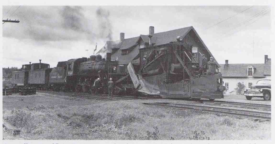
---ABOVE: Canadian Pacific’s D10 Ten-Wheeler No. 806 is assigned to work
with a Jordan Spreader. This photo was made at Debec Junction, New Brunswick,
on October 3, 1956.
The Jordan’s natural advantage over digging equipment that does not ride on the rails is the uniformity and stability afforded by the guiding tracks and the machine’s relatively heavy weight. This benefit is especially valuable when plowing or ditching on curved track, as the Jordan can easily maintain a consistent profile. A late-era Jordan Type A weighs about 130,000 pounds, which means it is unlikely to be disturbed by normal ditching duties. The blades are made of extremely tough manganese alloy steel, and are resistant to breakage.
Like the Titanic, however, the Jordan is not invincible, and the operator must know the limits of his machine. An efficient operator will let the Jordan do its work, allowing a reasonable margin of safety, without being overly cautious. One thing the Jordan is not suited to tackle is large rocks. These are likely to damage the machinery and are best re moved before the spreader is set to work.
The early Jordan Spreaders didn’t have a protective cab for the crew. Later machines had a small centrally situated cab. Eventually the cab was enlarged and moved forward to give the operator a better working environment and improved visibility. The four models of spreaders built in later years were the Standard, a relatively small machine discontinued in the 1960s the Roadmaster, which was a little larger the Type A Jordan; and the Type J Jordan. One of the biggest changes in the basic design of the Jordan Spreader was the introduction of hydraulics in the 1950s. Still, even after hydraulics were offered, Jordan continued to build the older pneumatic style of machines. In the world of modern track machinery, where electrical and hydraulic control are the norm, an air-controlled machine seems terribly primitive.
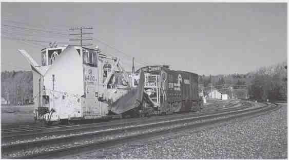
---ABOVE: Conrail’s Jordans were painted bright safety yellow and equipped
with large snow-service plows. This Jordan is seen along the former Erie
Railroad Buffalo Line at Attica, New York, on May 8, 1988.
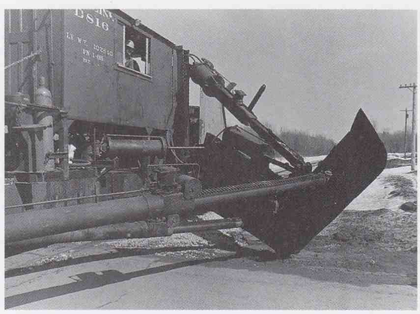
---ABOVE: On March 23, 1973, a Soo Line Jordan has its wing extended and
lowered into position, ready to clear out a ditch along the right-of-way.
It is a traditional air-actuated machine dating from the steam era. Some
railroads still use Jordans despite the development of more modern equipment.