Since rails both support and guide trains, they are one of the most crucial components of track structure. A rail road can survive with minor ballast problems, a few broken ties, missing spikes, and cracked tie plates, but a single rail failure can cause serious derailments and crashes. As railways progressed and trains became faster and heavier, the consequences of broken rails became an ever more serious issue. By 1900, the advent of powerful steam locomotive designs, air brakes, and automatic signaling systems permit ted passenger trains to regularly operate at 80 miles per hour and faster. A derailment at such speeds can result in tremendous loss of life. Therefore, careful and thorough inspection of the tracks is essential for ensuring safe and reliable travel on the lines.
Traditionally, tracks and rails were inspected by expert track walkers, who regularly patrolled a Section of line on foot, looking for defects. This inspection would reveal most flaws in the track structure, since many types of defects are detectable through close observation. A track inspector could easily spot potential problems in the ballast, ties, and fasteners. He would make note of any defects, and the section gangs would make the necessary repairs without risk to trains or passengers. Unfortunately, not all flaws are visible to the naked eye. Among the most serious of the invisible defects are tiny cracks inside the rail, particularly the transverse fissure—an internal crack bisecting the width of the rail. This crack was especially dangerous because it was undetectable by traditional methods, yet it could cause the rail to break or even shatter under the weight of a train, causing a derailment.

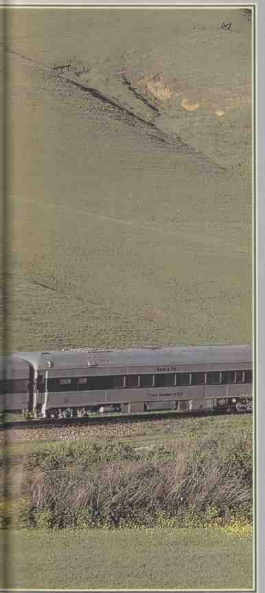
---ABOVE: Santa Fe did everything in style; even its track geometry train
had the appearance of a pocket streamliner. Spring is in the air, the grass
is green, flowers are blooming, and Santa Fe is preparing for its maintenance
season as its inspection train rolls westbound through Christie in California’s
Franklin Canyon.
In the years leading up to World War I, American railroads began to suffer the backlash of negative public sentiment, fueled by years of abuse of the public trust. Feuding rail barons, ambitious tycoons, rate wars, poor service, horrific crashes, and a general callousness toward passengers and shippers resulted in a tide of legislation aimed at curtailing railroad monopolies and mandating safer operations. Federal laws required the use of air brakes, automatic knuckle couplers, steel-framed cars, and other safety equipment to help make trains safer to ride and work on. Unfortunately, safety initiatives were often acted upon only in the wake of a disaster. In 1902, a terrible crash was caused by a signal being obscured by heavy smoke in the Park Avenue Tunnel in New York City. The crash led to laws that forced rail roads to electrify their New York passenger operations to eliminate smoke hazards. Similarly, in 1911, a horrific crash on the Lehigh Valley Rail road at Manchester, New York, killed 29 people and seriously injured another 60. This accident was attributed to that hidden menace: the transverse fissure. Like the causes of other major wrecks, rail fractures became a public issue. In an earlier era, such a disaster may have been shrugged off as unavoidable, but by this time action was required. In 1915, the Bureau of Standards initiated research to find a way to detect internal rail defects.
Dr. Elmer Sperry
One of the foremost inventors of the early twentieth century was Dr. Elmer Ambrose Sperry, a scientific genius who amassed more than 400 patents in his lifetime. He is probably best known for his gyroscopic inventions, including the gyro compass. He also designed electrical equipment for streetcars and early electric locomotives, and worked on designs for electric automobiles. Between 1923 and 1928, Sperry developed an induction system that was capable of detecting internal rail defects, including transverse fissures, and he founded the Sperry Rail Service. It was immediately successful, and he built a fleet of Sperry Rail cars to inspect American railroads for hidden rail defects. Sperry initially hoped to sell the defect detection cars directly to the railroads, but he eventually concluded that it would be more practical to run a company that used the cars as a contract service for the railroads. While railroads today routinely contract many specialized ser vices to outside vendors, in the late 1920s this was a relatively unusual practice. Railroads tended to be self-sufficient enterprises, keeping most of their maintenance work in house. Dr. Sperry died in 1930, but by the end of that year Sperry Rail Service had 10 large defect detection cars in operation, as well as a fleet of smaller rail defect detection equipment.
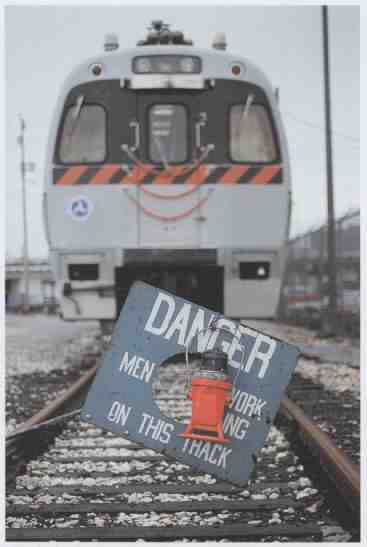
--- ABOVE: The Federal Railroad Administration (FRA) plays a major role in
inspecting and monitoring track conditions in the United States. The FRA’s
T-10 inspection car is shown here in a siding at Houston, Texas. The track
is “blue flagged” to prevent unauthorized people from moving a train or
equipment while it is being serviced. Tom Kline
Sperry’s Yellow Doodlebugs
Sperry Rail’s large defect detection cars, known in the industry simply as Sperry cars, were built from self-propelled gasoline-electric cars and called “Doodlebugs.” Doodlebugs were built for passenger service. The single gas-electric cars were cheaper to operate than a steam locomotive, and in the decade prior to World War 1, gas-electric cars were a popular way for railroads to cut costs on branch-line passenger operations. The market for gas-electrics sagged during the war years, but enjoyed a healthy resurgence in the 1920s. Most American railroads bought Doodlebugs and assigned them to lightly patronized operations. A number of manufacturers built gas-electrics, including J. G. Brill, and the St. Louis Car Company. The Electro-Motive Corporation was one of the largest producers of gas- electric cars, although it didn’t actually build the cars itself, but contracted the assembly to other builders. Electro-Motive was later bought by General Motors, and evolved into America’s fore most diesel-electric locomotive manufacturer.
For the first large defect detection cars, Sperry bought new gas-electrics from J. C. Brill and outfitted them with detection equipment and living quarters for the crew. By the early 1930s, passenger business was in serious decline, and many railroads were discontinuing lightly patronized and unprofitable passenger services, resulting in a surplus of gas-electrics. As Sperry’s business grew, it acquired many additional gas-electric cars secondhand from railroads. The gas-electric had largely vanished by the late 1960s, and later Sperry detection cars we home-built by Sperry Rail. Over the years Sperry amassed a roster of more than 25 self-propelled cars, many of which began their service lives gas-electric-cars for various Class I railroads including Seaboard Air Line, Baltimore Ohio Lehigh Valley, and Chicago & North Western.
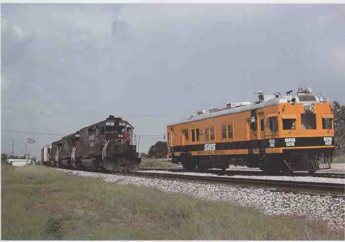
---ABOVE Built from self-propelled gas-electric cars known as “Doodlebugs,”
Sperry Rail Service’s yellow inspection cars have been a common sight along
America’s railways for many years. Sperry No. 126, photographed at Fulshear,
Texas, on July 17, 1997, retains some of its gas-electric character, including
the old “cow catcher”— style pilot.
---ABOVE: Dr. Elmer Sperry’s induction testing revolutionized the way railroads
search for hidden rail flaws. The black-and-yellow Sperry railcar has been
an institution on American rails for more than 70 years.
In the process of outfitting secondhand cars for defect-detection use, Sperry greatly altered their appearance, removing seats, blanking up windows, and adding the assorted equipment needed for rail testing. The traditional gasoline engines were gradually replaced with more modern diesel engines. The Sperry cars are typified by their striking yellow-and-black paint scheme, which has been used in one variation or another for more than five decades. Sperry’s self-propelled detection cars are numbered in the 100 series. Numbers 143 through 149, and car 200, are all home built; many of the earlier 100 series cars were constructed from gas-electrics or other rail road equipment.
Although Sperry is moving away from the larger detection cars, it still employs about 23 of them. The large cars are self-sufficient, and they are among the last examples of railroad equipment fitted with living spaces for the crew. (At one time the common caboose, among other pieces of equipment, was a home away from home for railroad employees, but the days of rail road crews living on their cabooses ended years ago.) The nature of the work brings Sperry cars all over the country, and gives their crews the opportunity to see many different places. Some cars are assigned to a specific region where they perform most of their testing; others travel far and wide. The crew often stays with the car for months at a time while it is on the road. After a full day of testing out on the line, the car ties up overnight on a siding or in a nearby railroad yard.
In addition to the testing and propulsion equipment, a Sperry detector car has a comfortable living space. Each car is designed to accommodate three or four Sperry employees. At the front of the car is the motor compartment, behind it is the galley where meals are prepared, and beyond that is the dining and lounge area. The middle of the car is equipped with upper and lower berths, a toilet, and shower facilities; a generator and storage space are found toward the rear of the car. The detection equipment, recording apparatus, and work area are located at the far end. An employee monitors the detection equipment checking for rail defects as the car rolls along the tracks.
The business of rail testing grew rapidly in Sperry’s first few decades. In 1930, after less than two full years in business, Sperry Rail Service had tested 36,000 miles of track. Twenty years later, the company had tested more than 2,000,000 miles of track on 124 different railroads. Quite an accomplishment for such a small company.

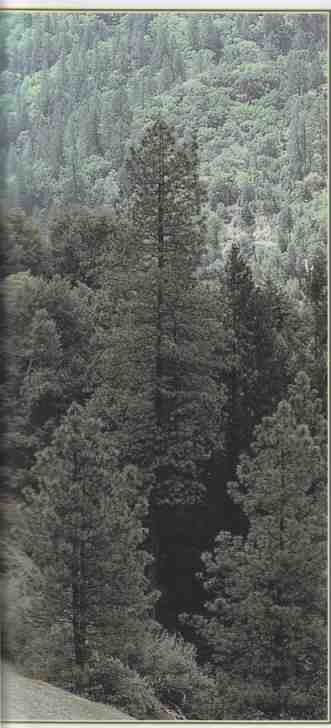
---ABOVE: Living on board the cars for weeks and months at a time, Sperry
crews are treated to some of the finest scenery in the United States. Here
SRS 118 descends California’s Donner Pass, near Cape Horn, on April 26,
1991. This car was built for the Baltimore & Ohio in 1927.
Testing Methods
Every defect that Sperry finds prevents a potential wreck. No one can ever really know how many derailments have been avoided, or how many lives have been saved by defect detection and preventative rail maintenance. The frequency with which different railroad routes are tested for defects varies greatly according to the level and type of traffic that is moved over the railroad, and with the needs of the owning railroad.
In their first two decades, Sperry cars employed a system using magnetic induction to test for defects. Then, beginning in the early 1950s, Sperry began augmenting the traditional induction tests with new ultrasonic tests. By the mid 1960s, all the big Sperry cars were equipped for both induction and ultrasonic testing.
The use of both systems allows the detection cars to locate a greater number of rail defects and with a greater degree of accuracy. Magnetic induction tests are most effective on the rail head, and may not reveal flaws in the body of the rail. In addition, some rail defects, such as fatigue cracks, may be disguised by other imperfections and are not revealed by induction testing. Bolt head cracks at the end of rails are among the defects that can be detected more reliably by the ultra sonic system. Sperry often uses ultrasonic inspection to complement its traditional testing, and both systems have proven useful for a thorough rail inspection. If a defect is found with one system, it can often be confirmed with the other, an especially important feature considering that many defects are invisible to the eye.
Induction Testing
Induction testing creates a powerful magnetic field in the rail, using large amounts of low-volt age current. Electrical brushes contact the rail to set up the magnetic field, while a sensing coil detects changes in the field that may indicate the existence of a rail flaw. Changes in the field are logged on a paper strip chart with automatic pens. Traditionally, one pen recorded changes in the field for each of the two rails. A highly skilled operator monitors the strip chart and interprets the incoming data. Magnetic induction can detect transverse fissures, but it also senses other imperfections in the rail, many of which are not serious. Corrosion, seams, and joints are all revealed by induction testing, so it is important to distinguish these from the more serious defects. When testing, Sperry cars roll along at just 6.3 to 13 miles per hour. When a potential defect has been located, the car stops and a crewman gets out to inspect the problem area and mark it for repair if necessary. Minor problems are indicated with yellow paint, more serious flaws with red paint. A railroad official typically rides along with the detection crew, and a repair gang shadows the car to make spot repairs.
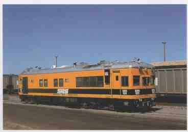
---ABOVE: Sperry No. 129, seen here on the Montana Rail Link at Helena, was
built by the Electro-Motive Corporation and St. Louis Car Company for the
Lehigh Valley Railroad in 1925. The ultrasonic detection equipment is visible
between the wheels of the car.
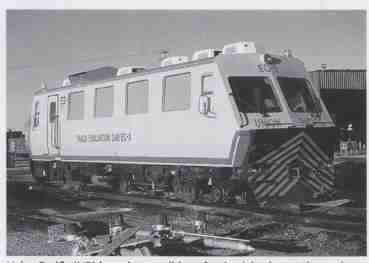
---ABOVE: Union Pacific (UP) has a long tradition of maintaining its own
inspection cars. UP’s Plasser EC-3 track geometry car is seen at Houston,
Texas, on February 20, 1988, when the car was brand-new.
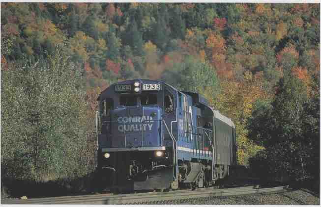
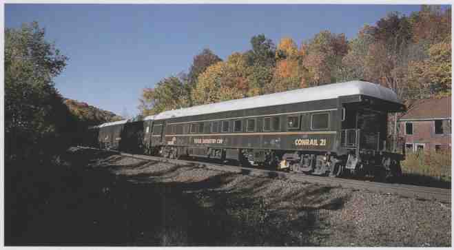
--- ABOVE: For years Conrail operated its own track geometry train. The train
consisted of two traditional passenger cars equipped with track geometry
measuring and recording equipment. Conrail’s No. 1933, a General Electric
B23-7 locomotive, was semi-permanently assigned to the track geometry train.
On a splendid October 7, 1997, the train rolls west on the old Boston & Albany
mainline at Becket, Massachusetts. Conrail’s track geometry train was a
regular visitor to the B&A each autumn.
Ultrasonic Testing
While the big Sperry cars still do induction testing, Sperry has gradually advanced its ultra sonic technology since it was first introduced more than 50 years ago, and major improvements in ultrasonic testing have made that system much more useful than it was in the early years. Sperry’s first all ultrasonic railcar was built for the Ne York City Transit Authority for use on the city’s subway system. This car was made from a Mack railbus built for the New Haven Railroad.
In ultrasonic testing, transducers project high- frequency sound impulses into the rails and rail joints. The reflection of the sound is recorded, giving inspectors an image that reveals internal and external rail conditions. Manual ultrasonic tests were performed before it was practical to do ultrasonic testing from the Sperry car. A number of hurdles needed to be overcome before the cars could perform rolling ultrasonic tests. For example, early ultrasonic systems were easily affected by the presence of grease on the rail. The introduction of automated compensation systems solved this problem.
The typical transducer is coupled to the rail using a Roller Search Unit (RSU), which is basically a fluid-filled tire that rolls along below the car. Inside the RSU are three transducer heads that project sound at three different angles. The different projection angles optimize the information that can be obtained from the inspection, similar to the visual effect of three cameras aimed at the same spot from different angles. The signal from the different heads is amplified, processed, and combined electronically to provide the most accurate rail profile traditionally the ultrasonic system was monitored in the same basic fashion as the induction system, using ink pens and paper strip charts. Taking ultrasonic impulses from three different angles also minimizes detection errors caused when routine imperfections, such as nor mal bolt holes, are mistaken for actual flaws. Still, extra attention must be given to bolt holes, because these areas are especially subject to stress- related fractures. Different parts of the rail have different inspection requirements. The joint areas are particularly important, as they have unusually high stress and are prone to different types of flaws than the rest of the rail.
The advances in rail defect technology have helped railroads reduce the number of defects and repair problems before they lead to accidents. Though the railroads run far fewer trains than they once did, most mainlines carry significantly more tonnage than they did 50 years ago. Trains are longer and heavier than ever before, placing much greater stress on rails and track structure and making defect detection extremely important.

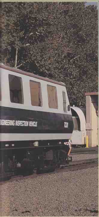
---ABOVE: Long Island Rail Road No. TC81 is a specially equipped
Plasser-1 20 track geometry car designed for work on suburban electrified
lines in the New York City metropolitan area. It is seen here at Metro-North’s
Maintenance of Way repair shop in North White Plains, New York on September
28, 2000.
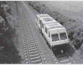
---ABOVE Plasser track geometry cars are versatile and adaptable, allowing
them to be used by railways all around the world, including Iarnród Eireann
(Irish Rail). larnród Eireann tracks are 5-foot, 3-inch gauge, but the
loading gauge is restrictive by both American and continental European
standards.
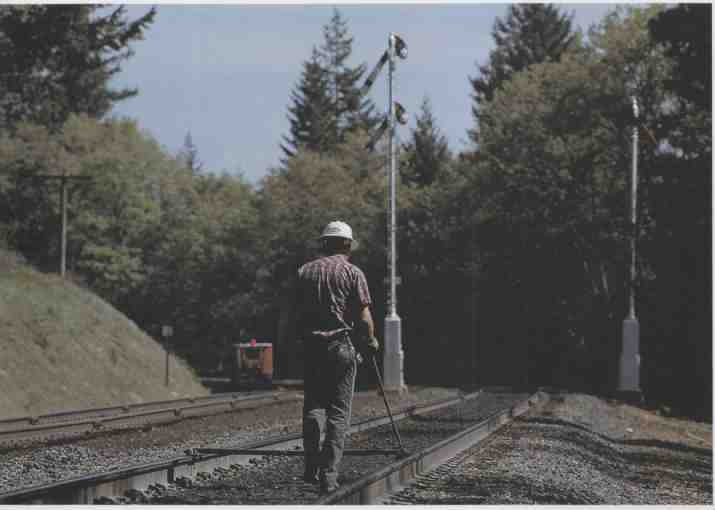
---ABOVE: Measuring the gauge on the Southern Pacific at Siskiyou Summit,
Oregon. The standard track width in North America, Britain, and most of
Europe is 4 feet, 8.5 inches. While some minor variation in gauge can be
tolerated, any significant deviation must be corrected.
Hyrail Detection Trucks
In addition to its large railcars, Sperry also has a fleet of Hyrail trucks (see Section 6). For many years, the trucks couldn’t carry induction equipment and were limited to ultrasonic testing. Recently Sperry has developed a new induction system for use on its Hyrail trucks, and built a prototype truck capable of doing both types of testing. Eventually Sperry hopes to retire many of its older railcars, some of which are now more than 60 years old, and replace them with dual- inspection Hyrail trucks. Today’s railroads prefer Hyrail vehicles because they are easier to get on and off the tracks. This gives a railroad greater flexibility when testing, as the truck can be taken off at almost any highway grade crossing, and doesn’t need to tie up the tracks as severely as the big cars. This is an important consideration for modern railroads, which are trying to squeeze as much tonnage over as little track as they can. The less time track is out of service for testing, the better.
Although the Hyrail detection vehicle will largely supplant the traditional Doodlebug” detector car, Sperry will not replace all its big cars. There are still some situations where they are preferred, such as remote lines, where there are very few grade crossings and no local accommodation, as well as heavily traveled passenger routes, such as the Northeast Corridor. Lines in remote regions of Canada will probably remain the stomping grounds for traditional Sperry cars for years to come.
Sperry Rail Today
Today Sperry Rail Service is a division of Rockwood, one of the world’s fastest growing materials engineering and inspection companies. Among Sperry’s customers are several of the large North American railroads, including Canadian Pacific, CSX, Norfolk Southern, Burlington Northern Santa Fe, and Amtrak. Recently Sperry expanded its international market and started serving SJ, Sweden’s national railway. Sperry Car No. 200, built new by Sperry in Danbury, Connecticut, was shipped to Sweden in May 1999. The car is manned by Sperry crews searching for defects on SJ. Sperry hopes to further expand its business in Europe and Asia and is looking at Eastern Europe as one of the best emerging new markets for its services.
Although Sperry Rail Service is the most prominent rail defect detection service, it is not the only one, and several other companies also offer a rail defect detection service; among the most prominent are Harsco and Herzog. Sperry is the only company that offers both induction and ultrasonic testing. A few railroads also perform their own testing instead of contracting the work to outside services.
== ===
Preserved Sperry Cars
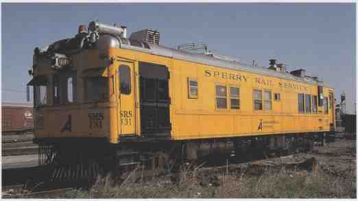
---ABOVE: Car No. 131, displaying an older variation of Sperry’s yellow-and-black
paint scheme, was built in 1925 for the Lehigh Valley, operating as its
No. 27, and went to Sperry in 1941. The traditional pilot is still apparent,
pictured here at Dolton, Illinois, in 1983.
Sperry cars are among the last active examples of Doodlebugs in North America and they are sought by museums when they are retired. In the 1980s, Sperry donated car No. X107 to the Railroad Museum of New England, now located at Waterbury, Connecticut. There are plans to fix up the car and display it as a Brill Doodlebug. The preserved X107 has a unique history. Originally numbered 107, it was built new by J. G. Brill and assembled at New York Central’s West Albany shops in 1930, and Sperry equipped the car with induction testing equipment. It was one of a few cars that fulfilled Dr. Sperry’s original business plan, and unlike the majority of cars that were operated by Sperry as a service, No. 107 was outfitted as a test car and operated by the New York Central. (New York Central and Union Pacific adhered to a self-sufficiency principle and preferred to do their own defect testing. Union Pacific still maintains its own defect detection cars.) With New York Central, the defect car carried the number X8015. It was 73 feet, 4 inches long, and powered by a 300- horsepower engine. An auxiliary 28- horsepower gas engine powered a 200-amp generator for generating the magnetic field. For almost 40 years X8015 worked New York Central rails, searching for defects and preventing accidents. In 1969, shortly after New York Central and the Pennsylvania Railroad merged to form Penn Central, Sperry reacquired the car, numbering it X107.
New York Central operated another gas- electric in non-revenue service as a clearance detection car. This car, No. X8016, was built in 1928 as a standard Brill Model 500 car. Unlike the X8015, it spent nearly three decades in passenger service before being transformed into a detection car by Central’s Beach Grove ( Indiana) Shops in 1955. Originally numbered M-10, it was powered by a pair of Brill 250- horsepower engines (thus the Model 500 designation) and had seats for 65 or 66 passengers. As a clearance detection car, most of its side windows were blocked up, and it was equipped with feelers on its sides and roof. It was used to measure minimum loading—gauge clearances.
Other Sperry cars have been candidates for preservation, including car 140, built in 1966 using the shell of a New York City Transit Authority R-33 subway car. In September 1976, this unusual Sperry car was sent to Australia, where it worked until it was retired in 1990. In May 2000, the car was moved to the Dorrigo Steam Railway & Museum in New South Wales.
=== ====
Track Geometry Cars
The growth in the size and weight of trains has placed ever greater pressures on railroad infrastructure, while the mechanization of railroad maintenance has drastically reduced the number of employees needed to repair tracks. As a result, it is now more important than ever before to en sure that tracks and right-of-ways are maintained to proper standards. The operation of track geometry cars is an integral part of a modern railroad’s maintenance program. These cars help railroad managers make maintenance decisions based on detailed, accurate, and up-to-date information. The car’s precise record of a line reveals potential future trouble spots as well as existing flaws. The cars are also used for judging maintenance quality when it is completed. Among the factors that a track geometry train measures are track gauge, profile (vertical change in the rail), and alignment (horizontal change in the rail). They also measure and record the degree of curvature, where a curve begins and ends, the amount of cross level (a measure of superelevation in curves), and the speed limitations imposed by a curve. In addition, they record the locations of crossings, switches, and other complicated track arrangements, providing a comprehensive data base for future reference.
As with locating rail cracks and defects, track geometry measurement was traditionally within the realm of track walkers and local maintenance supervisors. By inspecting ties, spikes, and ballast conditions, the track walker looked for gauge imperfections and other abnormalities. Signs of unusual rail wear, loose spikes, and evidence of rail motion were signs that the tracks might not be holding up under load. Although his years of experience would often allow a track walker to identify areas in need of attention, even the best trained track walker couldn’t identify everything that was wrong with the track, nor would he be able to accurately record every foot of mainline track for later analysis.
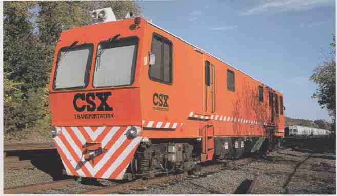
---ABOVE: The CSX EM-GRMS track car one of the most advanced detection cars
on the railroad today. It is jointly manufactured by ENSCO and Plasser
American. The body of the car is based on Plasser’s PTS-62 track stabilizer
car.
Many railroads regularly operate their own track geometry trains. A traditional geometry train was often a semi-permanently coupled two-car consist hauled by a locomotive. Old passenger cars were commonly converted into track geometry trains by outfitting them with specialized sensing and recording equipment. These trains would make routine scheduled trips over the line, recording the state of the tracks and right-of-way. For example Conrail’s track geometry train consisted of two heavyweight passenger cars painted in dark “ Pullman” green with yellow lettering that clearly identified it. It was almost always assigned the same locomotive, General Electric B23-7 No. 1933, as it made its yearly rounds across the system.
Over the years, the technology for track geometry measurements has made great progress. Today’s track geometry cars use a variety of sophisticated technology to measure and record track conditions as they roll along. Laser technology, video cameras, and precision computerized measurement provide a level of detail that was not available in earlier eras. The coupling of video imaging with older measurement systems has resulted in a new breed of track geometry cars that permit high-speed analysis of track conditions. The Federal Railroad Administration’s instrumentation contractor, ENSCO, has developed technology that is capable of operating at speeds up to 125 miles per hour for testing on Amtrak’s Northeast Corridor. In addition to analyzing track conditions, ENSCO cars can provide a profile of the overhead electrified catenary (the network of wires used to provide electricity to power the trains).
Plasser EM-120
Plasser American produces a line of Engineering Inspection Vehicles, which not only measure track geometry but may fulfill other elements of railway maintenance as well. Among these is the EM-120, a self-propelled car 49 feet long, 10 feet wide, 13 feet tall, and weighing just 58.5 tons. These dimensions conform to the loading-gauge of most standard track gauge—railways in North America and around the world, making the car adaptable for operation on many different types of railways. Like other track geometry cars, the EM-120 measures and plots the distance between the rails and assesses rail wear, while calculating rail profile, alignment, super-elevation, and gauge changes. As with other modern track geometry cars, the EM-120 uses a laser measurement system. Lasers project a light envelope on both sides of the running rails and measure the shadow to assess the level of wear. Computer analysis then determines the amount of wear by width and height, the angle of the rail to the roadbed, and the amount of railhead extension beyond its normal cross section, sometimes described as the rail lip. Rail measurements typically are made every 6 feet as the car travels along at speeds of 40 to 60 miles per hour. Track geometry measurements are plot ted on a graph for later analysis. In addition to the graphing, notable defects in track geometry are noted in special reports that indicate the location, length, and degree of seriousness of each perceived defect. To further aid in track assessment, the car is equipped with video cameras that make a detailed tape of the track. Location information, such as the railroad milepost, is superimposed on the video image to give track maintainers a solid frame of reference when looking at the tape.
The EM- 120 can be equipped with a thermal imaging system designed for analysis of electrified third rails. Such specialized cars can be used by suburban railways and transit lines with third- rail electrification. For example the Long Island Rail Road operates a Plasser-120 No. TC8I on its suburban electrified lines in the New York City metropolitan area. The Long Island has the most extensive third-rail electrification in the United States, and one of the highest passenger ridership of any railroad in North America. The thermal imaging system employed by Long Island on its TC8I is based on the technology used for military night-vision goggles, which create a visual picture from temperature readings. The infrared scanner is mounted on the nose of the car, and is designed to allow both panning and tilting adjustment to give the best coverage of the tracks. The thermal images are recorded on videotape and routinely analyzed by a computer. Though a defect in the third rail is unlikely to cause a derailment, as would a typical rail defect, it can cause serious disruptions in service.
Every year, the Long Island’s TC81 makes four complete inspections of the railroad’s main lines, and it checks major junctions and yard facilities twice a year. The car is designed to issue three categories of defect reports, according to the level of seriousness of the defect: The first are the parameters set for passenger comfort, the second is the railroad’s own safety requirements, and the third is the Federal Railway Administration’s requirements. The Long Island Rail Road is looking to improve its track geometry detection with a new car that will incorporate differential Global Positioning System (GPS) technology and the Gage Restraint Measurement System (GRMS).
Gauge Measurement
One of the most modern varieties of railroad detection cars uses the Gage Restraint Measurement System (GRMS) to evaluate track conditions, plan the replacement of ties, and judge the effectiveness of track maintenance programs. The standard track gauge on American tracks is 4 feet, 8.5 inches, and wheel flanges on normal railway wheels allow for some variation in gauge without risk of derailment. Still, track that is out of gauge is one of the top-five culprits of modern railroad derailments. A report by Gary A. Carr and Cameron Stuart indicates that 1,838 accidents involving gauge widening were reported by the Federal Railroad Administration between 1984 and 1990. The vast majority of these were the result of missing or defective ties or rail fasteners. A passing train places tremendous vertical and lateral forces on track, which can cause the rails to spread enough to cause the wheel to drop between them. This situation is most acute in curves, where centrifugal force puts added stress on the outside rail.
As with the detection of other track flaws, the traditional methods of looking for gauge deficiencies eventually became ineffective for modern railroads. Simply measuring the distance between the rails using conventional track gauging devices does not reveal fundamental structural flaws in the track that can result in a gauge-widening derailment. While track inspectors may take careful note of the condition of ties, tie plates, and fasteners, there is still an untold story. Gauge widening can be caused by a combination of conditions, including cracked and deteriorated ties, broken tie plates, and loose spikes. It is not always cost-effective, however, to constantly repair every visual flaw in track, so guidelines have been drawn up that aid in assessing track conditions. A single rot ten tie is not going to cause a gauge-widening incident, but at some stage, enough rotten ties in a given section of track can lead to problems. The speed and weight of trains and the level of traffic on a section of track are significant considerations in determining whether repairs are warranted. Each class of track has a certain level of flaws that are permissible. The evaluation of track is largely subjective, and each inspector has to use his own judgment in determining track conditions. Furthermore, some flaws are invisible to visual detection and go unnoticed. A vital consideration in effective gauge evaluation is that a heavy train presents a very different set of track conditions than exist on track without a train on it. Thus evaluating empty track provides a skewed analysis from the get-go. The development of GRMS is a vast improvement over conventional methods because it simulates the forces of a heavy train on track during the evaluation to provide a more accurate assessment.
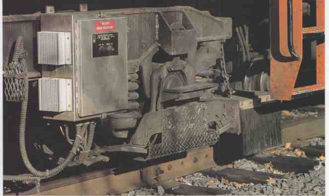
---ABOVE: The EM-GRMS uses the Gage Restraint Measurement System, which has
a hydraulically powered adjustable split-axle device to apply large amounts
of lateral pressure on the rails. The GRMS simulates the effects of a passing
train in order to evaluate track gauge under load.
The GRMS uses a special hydraulically powered adjustable split-axle device to put pressure on the track while special sensors monitor responses in the track. The split axle places 14,000 pounds of lateral force and 19,000 pounds of vertical force on the tracks in order to make measurements. This may seem like a fairly strong pressure, but the amount of lateral and vertical force is somewhat less than would be applied by an actual train. To compensate for the differences, an onboard computer extrapolates the data to paint a more accurate picture of how a train stresses the tracks.
The GRMS is used by a special track geometry car, designated EM-GRMS, that is manufactured jointly by ENSCO and Plasser American. The body of the car is based on Plasser’s PTS-62 track stabilizer car. It is 60 feet, 7 inches long; 9 feet, 3 inches wide; and 14 feet, 9 inches tall; and it weighs 80 tons. In addition to its GRMS functions, the car measures rail alignment, cross level, and the longitudinal profile of the rails. The EM-GRMS is powered by a 440-horsepower engine and is designed to take track geometry readings at speeds up to 50 miles per hour; when using GRMS, the car is limited to 35 miles per hour, remarkably fast considering the type of work it is performing.
The EM-GRMS outputs information for operators and track managers to study, while also marking serious track defects on-site using white and yellow paint. Areas marked with only white paint are less serious and are intended to flag the defect for further inspection within 30 days. Places marked with yellow paint or both white and yellow paint indicate serious gauging problems that need immediate corrective action. As stated earlier, the standard American track gauge is 4 feet, 8.5 inches. The white paint marks indicate that the gauge of the track under load is up to 4 feet, 10 inches, while the yellow paint designates loaded track gauge that exceeds 4 feet, 11 inches, or 2.5 inches wider than normal. Track this wide presents a high risk of derailment. Routine information obtained from the EM-GRMS can be used by railroad maintenance crews during scheduled track maintenance and can help identify ties that need replacing and related work.
Federal Railroad Administration
In the United States, the Federal Railroad Ad ministration (known universally in the industry by its alphabet soup—style three-letter abbreviation, FRA) is responsible for setting and enforcing rail road safety standards. Since 1966 the FRA has performed automated safety inspections of American railroads. These inspections are important for monitoring compliance with Federal Track Safety Standards and helping the railroads to identify problem areas and plan maintenance programs.
Track safety inspectors use the FRA’s Automated Track Inspection Program (ATIP) to identify potential track problems on key routes. Every year the FRA’s ATIP inspects 25,000 to 30,000 miles of the American railway infrastructure, including lines served by Amtrak, routes deemed of strategic military importance, and routes used to transport hazardous materials, such as depleted nuclear fuels.
The FRA classifies track using strict standards to set maximum speeds for freight and passenger trains. The faster the class of track, the tighter the FRA standards. The lowest grade of track is Class 1, which allows a maximum speed of 10 miles per hour for freight and 15 for passenger trains. By contrast, Class 4 track permits a maximum speed of 60 miles per hour for freight and 80 miles per hour for passengers. In addition to meeting track geometry parameters, the faster classes of track also have to adhere to other safety requirements, such as signaling to protect against collisions.
In 1981, the FRA began using a special track geometry car designated T-10 for its Automated Track Inspection Program. This car was based on a Budd-built, diesel-powered SPV- 2000 railcar— essentially a modern-day equivalent of the old gas-electric car—which used the same type of curved stainless-steel body introduced on the original Metroliners in the late 1960s and employed on Amtrak’s Amfleet passenger cars. FRA’s T-10 was 85.3 feet long, 10.5 feet wide, 14.5 feet high, and weighed 70 tons, It was capable of traveling at a maximum speed of 80 miles per hour. The T-10 could measure eight different aspects of track geometry, plotting them on magnetic tape and an oscillograph. Like other modern track geometry cars, the T-10 used sensors to take measurements that were fed to onboard computers for analysis. It measured the profile and alignment of each rail, and the gauge between them, while calculating the cross level, curvature, and warp of the track and comparing this information with the FRA’s track safety standards.
To keep pace with changes in the industry and take advantage of new technologies, the FRA issued new safety standards in 1998. Among the changes were new requirements mandating more frequent rail inspections. An FRA press release dated June 25, 1998 explained…
“The new track standards permit each railroad to design its own electronic record-keeping system, as long as the system properly safeguards the integrity and authenticity of each record. Electronic record-keeping, which currently is allowed only through a lengthy waiver process, will aid railroads, as well as the FRA, in retrieving necessary information to assess the effectiveness of track maintenance programs.
“Under the old regulations, internal rail inspections were required once annually, with no consideration for highly utilized trackage. Under the revised regulations, the frequency of internal rail inspections will be deter mined by a combination of elapsed time and the tonnage accumulated over the track since the last inspection. In addition, the requirement will now apply to all Class 3 trackage, which is capable of sustaining freight trains safely at 26 to 40 miles per hour and passenger trains at 31 to 60 miles per hour. Under the old regulations, the internal rail inspection requirements applied only to Class 3 trackage over which regularly scheduled passenger trains were operated.”
In 1999, the FRA awarded a $3.7 million contract to ENSCO to produce a new state-of-the-art track car to replace the obsolete T-10. The new FRA vehicle was intended to take ad vantage of the latest developments, such as differential global positioning. At the time of the award, Federal Railroad Administrator Jolene M. Molitoris explained the benefits of the new car in a press release:
The new track geometry measurement vehicle will advance safety, which is President Clinton’s highest transportation priority. [The new vehicle] will enhance our track safety oversight capabilities and thus help assure safe movement, especially of passengers and hazardous materials.
Ultimately two new vehicles were constructed: a new self-propelled car, designated T-2000, to replace the T-i0 and a research platform, designated T- 16, for developing new track inspection technology. The T-2000 can travel up to 90 miles per hour under its own power, but it can perform tests at speeds up to 110 miles per hour when towed along in a train. The T-16 can work at speeds as fast as 150 miles per hour. The new cars were unveiled at Washington Union Station in November 2000, just a few weeks before the de but of America’s fastest passenger train, the Acela Express (which can travel at a top speed of 150 miles per hour in revenue service, a significant in crease over previous top speeds).
![]()
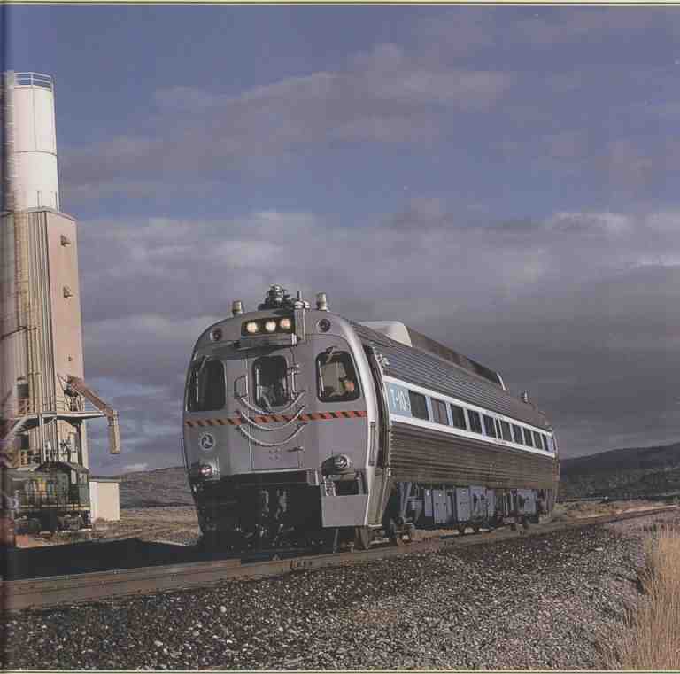
---ABOVE: The Federal Railroad Administration’s T-10 detection car rolls
past the Scoular grain elevator at Silver Bow, Montana, on September 6,
2000. After two decades testing American railroads, the uniquely designed
car is being replaced by more sophisticated equipment.