The West German politicians’ belief in railways in the 1980s (and subsequently) is in striking contrast to that of the British Cabinet, not least the visceral distaste for rail travel publicly expressed by the former British Prime Minister, Margaret Thatcher.
FINANCE AND FORWARD-THINKING
In the West German Federal Transport Plan, the Bundesverkehrswegeplanung (BWVP), a very large sum of money was budgeted for railways.
The creation of some new very high-speed lines, Neubaustrecke (NBS), and the up grading with automatic train control equipment of many existing routes, Ausbaustrecke (ABS), were given priority. In 1986 terms, by which time work was well in hand with the initial NBS, a total of the equivalent of $21 billion had been committed.
The cost of the new NBS lines is inflated by the very high cost of making them environmentally unobtrusive for the operation of new Inter-City Express trains at 250 km/h (155 mph) with a potential of 280 km/h (174 mph).
At the same time there was still a belief that Germany’s Transrapid Maglev system would be chosen for at least one route between two major cities. Transrapid is certainly not unobtrusive, because it uses an unsightly elevated guideway. So far it has been beset by problems and is not yet ready (as discussed in more detail in a later chapter).
Inter-City Express is now a reality. Two lengths of NBS were inaugurated in 1991 from Hannover to Wurzburg and Mannheim to Stuttgart, a total length of 430 km (267 miles).
The Hannover-Wurzburg line forms an important part of the Hamburg-Munich trunk route and, unlike France’s TGV, is routed through stations on the classic lines at important junctions, serving places such as Gottingen, Kassel and Fulda. This has involved a number of expensive civil engineering works, with flyovers and flyunders designed to give the NBS tracks a clear path. It is as well to remember that all of the major Deutsche Bundesbahn infra-structure projects, including electrification, are federally funded.
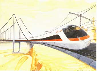
A designer’s prototype of a streamlined ICE power car. The train is depicted on a section of upgraded “normal” line.
To add to the two lines just opened, the Cologne to Frankfurt NBS is under construction. It is proposed to split the line at Eddersheim, between Wiesbaden and Frankfurt, so as to serve Frankfurt Airport, already pro vided with a three-track station handling 7.5 million passengers a year. A new station is planned to the east of the present station, and is expected to be completed by 1997. Until the new station is finished IC-Expresses will use the existing station. The Hannover-Wurzburg line is 326 km (203 miles) long and cuts through mountains and across deep valleys. Again unlike the French TGV, it is designed for mixed traffic, including fast freight, and has a minimum curve radius of 7000 m (23,030 feet) and a ruling gradient of 1 in 80 (1.25 per cent). The consequence of this is some 34km (21 miles) of bridges and 62 tunnels totaling 116 km (72 miles) — one of which, the Landrucken tunnel south of Fulda, is 10.75 km (6.5 miles) long. It is near the summit of the line which is 386 m (1270 feet) above sea level.

Equipment layout for ICE power car (locomotive). Includes: Power supply, line filter; Contactors, rectifier; Oil cooling system; Traction motor fans; Choke protection, rectifier; Electronics; Electrical control systems; Ancillaries, switchgear; Compressed-air equipment; Air-conditioning control system; Main-current static frequency changer; Measuring and diagnosis equipment; LZB; Transformer; Eddy current brake power supply
Technical Specs of ICE rail and locomotive, Germany:
|
GAUGE: Electrical system: |
Standard 4 ft 8½ in. (1435 mm) 15kv ac 16.6hz |
|
FORMATION: Power cars: Trailer cars: |
2+12 - max 2+14 2X4800 kW 12 |
|
BUILT: Builders: Number built: |
1990 onwards ABB, MBB, AEG, Krupp, MAN 45+ |
|
WEIGHTS: Power car: Trailers: Service car: Restaurant car: |
Full train: 784 tones (770 tons) 78 tones (76.6 tons) 52 tones (51 tons) 52.6 tones (51.7 tons) 55.5 tones (54.5 tons) |
|
DIMENSIONS: Power car: Trailers: Width: |
Full train — 357 m (1175 ft) 20160 mm (66 ft 1¾ in) 26400mm (86 ft 7½ in) 3020 mm (9 ft 10¾ in) |
|
SEATING: First class: Second class: Service: |
Full train: 500 approx 48 66 39 second class |
|
POWER EQUIPMENT: System: |
3-phase asynchronous ac –dc – 3-phase ac |
|
TRACTION MOTORs: Power car: |
8x1200 kW — total 9600 kW 4 |
|
MAX PERMITTED SPEED: Present service speed: |
280 km/hr (175 mph) 250 km/hr |
|
BRAKING SYSTEM: Emergency brake: |
DISC and regenerative Linear Eddy-current brake (experimental) |
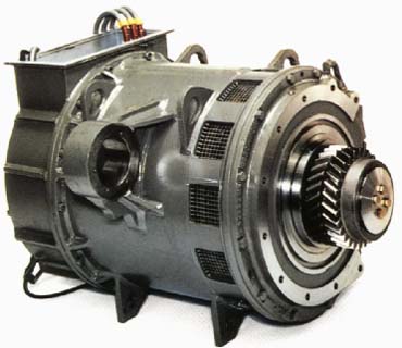
Image of one of the asynchronous, three-phase traction motors. Unlike both TGV and IC225 (British Rail Class 91) the motors are mounted within the bogie frames.
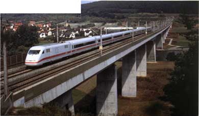
The characteristics of the Neubaustrecke are here clearly shown, as one of the new trains crosses a reinforced concrete viaduct having just emerged from a tunnel under the hill in the background.
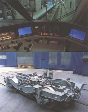
(top) A view through the driver’s cab windows. The two VDUs can clearly be seen, together with the excellent layout of instruments, switches and indicators. (bottom) A view of a power car bogie. The two traction motors can be seen near the center of the bogie between the two sets of secondary flexi-coil springs. The drive is taken through double- reduction gears to each axle.
THE TRAINS
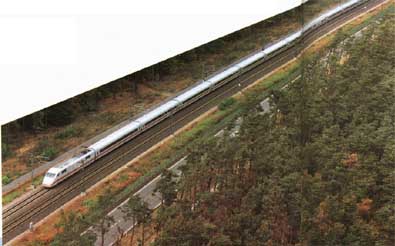
The picture shows a 2+13 formation on part of the Neubaustrecke, running alongside a main road. The fifth trailer from the rear is the “service” vehicle.
The forerunner of the IC-Express train sets was an experimental 5-unit train set, known as the Intercity experimental (ICE), which was first demonstrated to the public towards the end of 1985 during the celebrations of the 150th anniversary of the German Railways. The train was a joint development between the rail industry and the German Federal Railways (Deutsche Bundesbahnen), and was substantially financed by the Federal Ministry of Research and Technology (BMFT). The following objectives had to be met:
1. to investigate and test operation on specially prepared test lines at speeds up to 350 km/h (217 mph).
2. to demonstrate the ability to run with normal speeds up to 300 km/h (186 mph).
The five-vehicle train consisted of two identical stream lined power cars, two intermediate trailers with variable interior layouts, and a dynamometer car for technical records and measurements. The planned very high operating speeds made aerodynamic shape of importance in keeping energy consumption within bounds. And because a significant proportion of each new line would be in tunnels, it was equally important to reduce the effect of one train passing another at a closing speed of 500 km/h (310 mph) or more. The results of the tests are amply demonstrated in the production trains, where the pres sure sealing, if very expensive, is extremely effective.
Every aspect of the proposed new trains was extensively tested both on the line and in a special roller-rig at Munich. The first high-speed public demonstration was on 26 November 1985, when a speed of 317 km/h (197 mph) was attained. A year later on 17 November 1986 this was increased to 345 km/h (214 mph). This heralded a two-week examination of public opinion to test reactions to a number of special features. The ICE was run on the inter-city lines between Frankfurt-Munich and Frankfurt-Hannover when a representative group of passengers was asked for their views about comfort, design, passenger information systems and transfer of luggage. The answers were extremely valuable in finalizing the design of the production trains. It was also a useful marketing exercise to estimate the chances of winning passengers from other modes of transport. “Twice as fast as the car, half as fast as the plane” is the often repeated claim of Deutsche Bundesbahn’s ex-airline marketing manager.
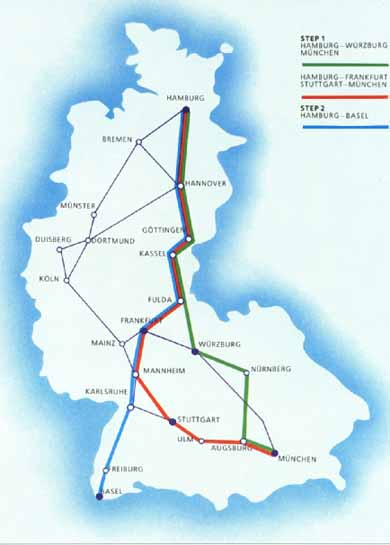
The ICE Network. Lineup of ICE train-set the maintenance depot. A new purpose-built depot has been provided which will service ICE only.
Following the ICE came the first 45 production train sets. The present makeup has two 4800kW power cars weighing 78 tones (171,600 lb), one at each end of eleven trailer cars. The power cars are driven by four asynchronous three-phase traction motors. There are three first-class cars, one restaurant/bistro, one service/ special compartment car and six second-class cars, although power is sufficient for the addition of another two trailer cars — to make 15 vehicles in all. The total weight of the present set, without passengers and lug gage, is 732 tones (719 tons) and the maximum design speed in service is 280 km/h (174 mph) for which the NBS lines are engineered. But for the time being the IC-Express timetables are based on a limit of 250 km/h (155 mph). Later, when sufficient experience has been gained, drivers will be permitted to use the higher speed to regain any time that may have been lost.
The traction control system is based on that developed by Brown Boveri and used in the latest DB Class 120 electric locomotives. An electronic data and diagnostic system is employed. This provides a standstill check prior to departure; a performance check during the journey; and diagnoses for maintenance staff to indicate the presence and location of a fault. Communication between man and machine is provided by displays with function keys. Apart from displays on the driver’s desk, individual cars are equipped with similar devices for use by the train crew and for technical staff In addition, there are inter faces for communication with remote terminals for maintenance purposes.
As noted in other chapters, current collection is a critical matter on very high-speed trains and was also one of the subjects covered by the ICE tests. A special design of current collector was evolved and each power car carries one. On the ICE, one collector was used to feed both power cars, which needs a high-voltage line along the roofs of the intermediate cars. The tests showed that even with only seven intermediate vehicles it was possible to use a collector on each power car and dispense with the high voltage line along the coach roofs.
PASSENGER VEHICLES
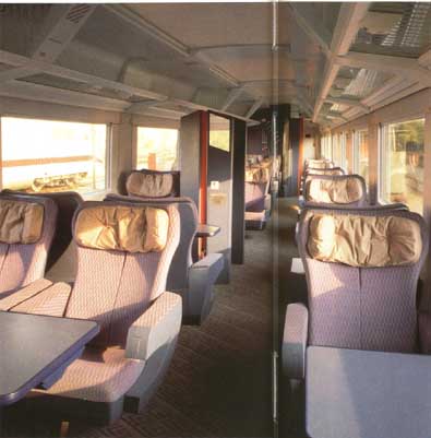
The interior of a first- class saloon. The section to the rear forms the side-corridor/compartment accommodation.
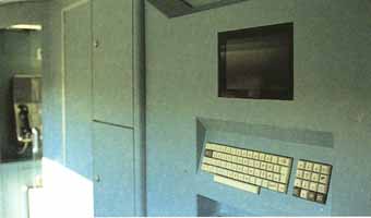
Passenger and train information is displayed on a screen similar to this. It can also be used to obtain hotel bookings, train reservations, and other relevant information.
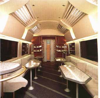
The buffet section of the “service” vehicle. Roof lights, as well as side windows, are provided to enhance the feeling of space.
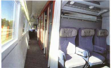
A view along the side corridor section of the first- class coach.
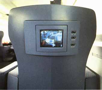
A video screen set into the back of a seat. The selection switches are to the right of the screen.
All of the passenger vehicles have aluminum bodies and run on bogies with coil springing. Later it is hoped to introduce air secondary suspension when further experimental work has been completed. The DB engineers do not consider that enough running at very high speeds has been done to establish the reliability of air springs under NBS conditions. Each passenger car is 26.4 m (86 ft 10 in) long. They are slightly wider than the normal DB cars at 3.02 m (9 ft 11¼ in). This gives a very spacious feeling, especially in first class. The service vehicle, half of which is a second-class saloon, has a small conference office, an office for the chief train conductor, catering crew room, telephones, toilet for the handicapped and electronic information displays. Both first- and second-class cars have some seating in compartments.
In-train entertainment has not been neglected. Each seat has a standard terminal for earphones — these can either be personal or hired from the train attendant for about $10.00. There are six channels, three for radio, three for on-board tapes. There is a further channel for video, visible on a small flat LCD full-color screen in the seat back of the smoking areas at the ends of the first- and second-class cars. There is a possibility that later DR will transmit live shots from cameras installed in the power car nose!
There are also two electronic displays in one vestibule of each car. One gives details of the train’s itinerary, alternating with the current speed and time of day. The other can be used to call up information on the German Federal Railways and their ancillary services. Some of this information is also available on the more elaborate panel in the service vehicle from which rail, hotel and other reservations can also be made.
As with other high-speed lines there is no line-side signaling. Instead, an automatic train protection system (ATP) is employed with in-cab signaling. This is a system developed for DB and has been proven on the normal high-speed main lines, where it is being installed for trains operating under the ABS auspices. It is perhaps unfortunate that each national railway system employing ATP has developed systems without regard to compatibility with each other particularly in view of the European high-speed network, not to mention the Channel Tunnel. The latter wilt open with high-speed trains running over the three systems of Britain, France and Belgium.
Next: Automated Railways, Metro Lines and Light Railways
Prev: TGV
Top of Page