Automation of railway operation is a feature of signaling systems, and such systems were installed on main lines as long ago as the first decade of this century. On underground railways, automatic signaling featured even before that. Today it is commonplace on all forms of rail transport.
Metro systems particularly lend themselves to auto mated operation. Automatic route-setting has long been a feature of London Underground lines, where track lay outs are relatively simple and trains with common characteristics are run to a clear-cut, repetitive pattern. Today on new Rapid Transit lines, computer-based automatic route-setting has been combined with other functions to produce fully-automated systems. In the mid-1950s, the Paris Metro began experimenting with a system designed to regulate the speed of trains over a specially equipped section of line. By the 1960s London Underground was experimenting with a system of automatic train operation (ATO), which was perfected and installed on the Victoria Line in 1968 71.
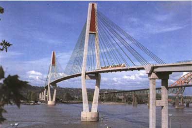
The new cable-stayed bridge, over the FraserRiver which
carries Vancouver’s Skytrain along the 1990 extension
to Scott Road,. is one of the largest of its kind in
the world.
WITH OR WITHOUT OPERATOR?
So far these systems still employed a train operator to ensure the train was ready to depart and to give a starting signal. From that point the train accelerates, runs, coasts and brakes to a stop at the next station controlled by computer and without any further intervention from the operator.
As long as there are operators and passenger regulation is ad hoc, station stopping times cannot be guaranteed. The ultimate in regularity can be guaranteed only with full automation and 100 per cent reliability, and the latter is rarely achievable. An unmanned fully automatic rail way has much in its favor if its users can be persuaded that it is “safe”.
The ultimate in automatic train operation is the totally unmanned train, and this was first achieved on the light rapid-transit system in Lille (the VAL system — Vehicle Automatique Legere — which opened in 1983) and in the Port Island system in Kobe, Japan, which began running shortly afterwards. The Kobe system is small by comparison with Lille. Today there are a number of fully auto mated people-mover systems, mainly specialized ones, for example at Gatwick Airport and Dallas-Fort Worth Airport. The Lille system is of particular interest because it is an urban Metro in its own right. There are two other systems of special interest, both with different approaches the Vancouver Skytrain and the London Docklands Light Railway.
VAL — THE LILLE METRO
In 1969 Lille New Town — Villeneuve d’Ascq — sought a suitable transport system for a link with the center of the city of Lille. The town authority, known now as EPALE, commissioned Professor Robert Gabillard of the Scientific & Technical Faculty of Lille University to recommend a modern transport system in keeping with the new development. Professor Gabillard recommended a fully automatic rapid-transit system with vehicles running on rubber tires for quietness, part elevated, part at ground level and part in tunnels.
When his principles were accepted tenders were issued, and Matra’s VAL system was chosen. Professor Gabillard and his team of academics and students acted as consultants. Matra Transport, who are signaling and automatic train control specialists, headed a group comprising its own automation company, Interlec; CIMT Lorraine as rolling stock builder; and TCO (Traction-CEM-Oerlikon) to supply the traction equipment (the two latter companies are now incorporated in GEC Alsthom).

The VAL System — Vehicle Automatique Légère — opened
in hue, France, in 1983 and is the first totally unmanned
train. A similar rapid-transit system was developed shortly after in Kobe. Japan.
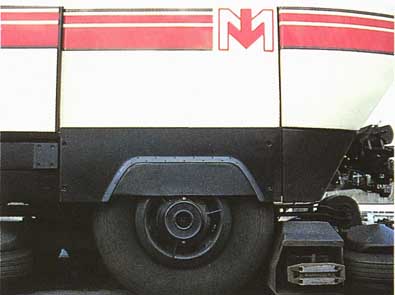
Two axles with rubber-tired wheels carry the pair of permanently
coupled car bodies. Each pivoting axle is equipped with steel runners
which come into use at switching points.
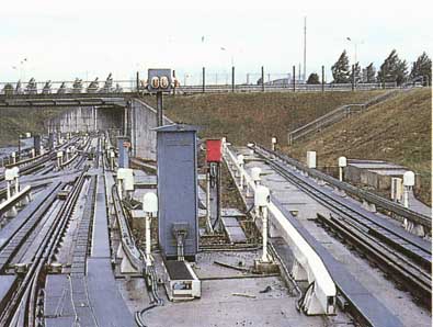
The train, moving along parallel concrete runways, is
guided by horizontal wheels which press against lateral guide rails.
The latter also conduct the electricity.
The length of the first line was 9 km (5.6 miles) and it was inaugurated on 25 April 1983 when President Mitterand visited Lille and the surrounding area. Public service commenced on 16 May 1983. There were 13 stations on Line 1 and the first, Quatre Cantons, is in the new town of Villeneuve d’Ascq, where the depot is also located. Because trains and stations are normally un manned, each station has continuous glass paneling along the platform edge with automatic sliding doors which remain closed until a train has come to a standstill. The doors are opened simultaneously with those on the train. Trains are halted Within an error of no more than 300 mm (11¾ inch).
The basic VAL vehicle is a pair of permanently coupled car bodies, each carried on two axles with rubber-tired wheels. Each two-car set is 26.14 m (86 ft) long and 2.06 m (6 ft 9 in) wide. There are three Metro systems outside Paris and all operate rubber-tired trains. The two earlier Metros in Lyons and Marseilles use the system developed by the Paris Metro with bogie vehicles. The Lille vehicles are therefore much smaller and they do not have the steel guide rails of the other two systems. Instead the single axles are equipped with steel runners which only have a function at switching points. Each axle is driven by its own 120kw motor mounted on the vehicle frame, and the drive is through a Cardan shaft. Each axle is free to pivot by a controlled amount.
The track for the carrying wheels is novel and consists of two concrete runways spaced 1.6 m (5 ft 3 in) apart. Guidance is provided by horizontal wheels which press against lateral guide rails, which also act as the positive and negative conductor rails supplying 750V dc to the vehicles. At switches, where there has to be a break in the lateral guide rails, the secondary guidance system comes into play. Two small rollers on each axle’s pivot point engage with a flexible steel blade, which can be set either for a straight run through or to guide the vehicle on to another track. On each side of the steel blades are two rails which ensure that the guide wheels are directed either side of the steel blades.
COMPUTER CONTROL
The vehicles are driven automatically using a two-way flow of information between the trains and the central control room; detection apparatus ensures that the position of vehicles is known at all times. Speed is controlled by two programs built into the track in the form of a pair of cables which cross over each other; the pattern of the crossovers determines the speed of trains. One program imposes the normal slowing before a station and the other a more rapid rate of deceleration when approaching a train ahead. By this means trains are allowed to follow one another without the need for an unoccupied “block section” between.
Real-time computer control provides flexible operation. Trains are dispatched from the terminals at two-minute intervals. At busy times extra trains are inserted, and the interval between trains can be reduced to 1 minute and station stops are regulated. Should a train get ahead of its schedule, it can be held at a station for up to 2 minutes.
If a train is running behind schedule, it can be speeded up. Four speed levels can be selected between 60 and 80 km/h (37-50 mph).
The depots are only part-controlled by computer because trains have to be moved into certain positions for maintenance. The non-automatic area is controlled by operators who move trains into the parking tracks of the automatic area where they are called into service by the computer. Each train has a small control panel at the front and rear ends so it can be driven manually for movements in and out of the workshops and into the automatic area.
CUSTOMER SERVICE
All stations on the elevated and tunnel sections have lifts for disabled people and mothers with pushchairs. There is no step up or down and only a small gap between the platform and the car doorway, making access by wheel chair easy. Escalators are installed at stations where there is more than 6 m (19 ft 9 in) downwards or 4 m (13 ft 2 in) upwards difference in level between the street and the platform.
Because rubber tires (tires) are employed, acceleration and braking rates are high and standing passengers are warned to remain in the entrance vestibules where there are vertical grab-poles. How wheelchair passengers cope has to be left to the imagination!
VAL System ( Lille, France)
SYSTEM: Type: Nominal gauge: Electrical system: |
Fully-automated, rubber tired Light Rapid Transit (LRT) 1.6 m (5 ft 3 in) 750V dc collected from guide rails |
TRAIN FORMATION: Powered cars: Number of axles: |
2-car units 2 2 |
BUILT: Builder: Number built: |
1982-9 — to be extended Alsthom 83 units |
DIMENSIONS: Width: |
26.14 m (85 ft 9 in) overall 2.06 m (6 ft 9 in) |
CAPACITY: Min headway: |
5000 passengers/hour 1 minute |
POWER EQUIPMENT: System: |
dc chopper Automatic driving |
CONTROL SYSTEM: Operating speed: |
Real-time computer 60 - 80 km/hr (37-50 mph) |
TRACTION MOTORS: Type of drive: |
4X 120 kW Cardan shaft |
BRAKING SYSTEM: Operating speed: |
Disc and regenerative Regenerative 80—10 km/hr 50—6.2 mph) |
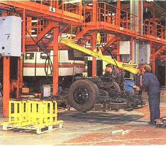
The VAL trains can be manually driven, so that they can be moved
into certain positions in the maintenance depots. Here. operators are fitting
a bogie.
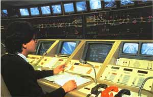
The computer control center can detect the position of vehicles
at all times. Speeds can be controlled, extra trains can be quickly summoned
if there is a fault, and a two-way public address system enables quick
response to passenger problems.
A MATTER OF TIMING
When a train stops at a station platform there is a delay of.1 second, during which time all conditions are checked for safety. If all is correct the train then gives a command to open the doors. Immediately a countdown begins, and after 14 seconds a start command is given by the station. An audible warning sounds, the doors are closed, and after a further series of checks the train departs and accelerates on its way. At busy times the station stop time is increased to 30 seconds, but the procedure remains the same. At the terminal stations trains make the normal station stop and are then run forward into a shunting neck. If all conditions are correct and the other platform is vacant, the points are switched and the train moves into the platform to take on passengers.
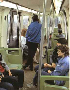
The trains, which have a maximum capacity of 208 passengers, can
carry some 10,000 people per hour in each direction. Wheelchair access
is straightforward, as platforms are flush with train doors, and vertical
handrails are positioned by the doors for standing passengers.
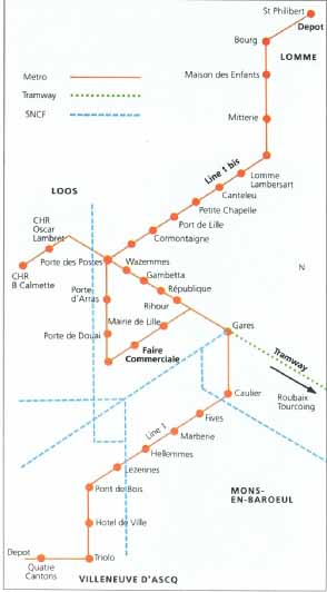
The Lille Transport System
EXTENSIONS
An extension 4.4 km (2.75 miles) long was opened in 1984. It has a further five stations and runs due south of the city to the Loos district. Following the success of the first line, a further 11.6 km (7.2 miles) were added with a further 18 stations in 1989. This line, known as Line 1 Bis runs from the main line station southwards through the commercial center, then turns west to an interchange with Line 1 at Porte des Postes, and then north-west to the Lomme district at St Philibert, where there is an additional depot.
Two more lines are planned and expected to be in operation by 1996. At Gares, the main line railway station, there is also an interchange with a light railway (former tramway) to Roubaix and Tourcoing, popularly known as Le Mongy. This line, which is of conventional type, is, like the VAL system, owned by the Transports en Commun de a Communauté Urbaine de Lille (TCC). It is currently being upgraded and routed to serve the new TGV Nord station.
At present, services are provided by 83 two-car trains. So popular is the VAL system that some 43.5 million passengers are carried annually. VAL systems are also being adopted or proposed for Starboard, Bordeaux (approved for 1996 opening), Rennes (approved in 1989) and Toulouse (10 km of initial route approved in 1985 for opening 1993), while other French provincial cities are said to be interested.
SKYTRAIN - VANCOUVER METRO
A Canadian company, Urban Transportation Development Corporation (UTDC) — founded and originally owned by the Ontario Government—was developing an Intermediate Capacity Transit System (ICTS) designed to cater for up to 25,000 passengers per hour in each direction. Its principal features included: fully automatic operation of lightweight vehicles working singly or, in married pairs, up to six-car trains; steel wheeled steerable bogies running on continuously welded rail (CWR) (see page 81); linear induction motor (LIM) propulsion and regenerative braking (see page 80); slender concrete elevated guide ways; and 600V dc power supply. Other features were quietness in operation, low acquisition costs, low operation and maintenance costs, traction independent of friction between wheel and rail, and the ability to negotiate sharp curves. Curves as sharp as 30 m (100 feet) radius are a feature. This was branded as Advanced Light Rapid Transit (ALRT). It is an interesting meld of metro, LRT and people-mover technology.
The first fully operational installation was a Metro feeder system, the Scarborough Line in Toronto, opened in 1985. A second line, the Toronto Harbourfront Line, opened in 1990, making a total of 9 km (6 miles).
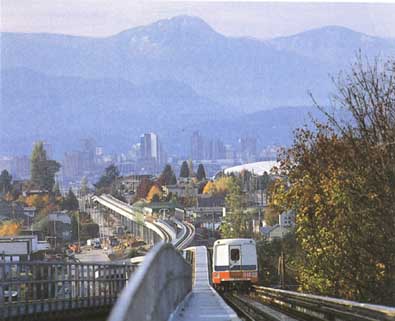
The lightness of the Skytrain vehicles (14 tons per car) means
that they can cope with curves down to 70 meters (230 feet) and 6 percent
gradients.
RIVAL PROPOSALS
Greater Vancouver, with a population of over 1 million in 1980, had had no rail transit for nearly three decades. The city was set to host Expo 86, a world exhibition on transport and communications. The citizens of Vancouver had successfully opposed urban motorways, and as long ago as the 1970s plans were developed for light rail ser vices along the right of way still owned by BC Hydro, a relic of the former extensive streetcar system abandoned in 1954. A traffic forecast on the route proposed to New Westminster indicated that with numerous light- controlled crossings LRT capacity would be inadequate.
Various possibilities were examined and a proposal from UTDC looked good. It made use of advanced technology in keeping with the spirit of Expo 86, and was fully auto mated. Its ALRT, now renamed Intermediate Capacity Transit System (ICTS), would provide the answer to a link between the two Expo sites on opposite sides of the town center using the long-disused former Canadian Pacific Dunsmuir single-track railway tunnel. The small size of the cars would allow two tracks in the tunnel, one above the other, and with gradients of 6 per cent (1 in 16.67) and curves of 70 m (230 feet) radius, the ICTS tracks could easily be fitted into the urban structure.
The ICTS system was 25 per cent more expensive than Light Rapid Transit for the whole route to New Westminster, but it was estimated that the improved quality of service would generate enough revenue to offset this difference — and more. Ministerial approval was given in November 1980 and a contract was awarded to Metro Canada (a division of UTDC) on 29 May 1981. Fast work was needed to complete the 21.4 km (13.3 mile) line in time for Expo 86, and what had been estimated to take seven years was telescoped into four. Many sections of line had to be planned in detail before planning consent could be obtained, and sometimes engineering planning had to be done two or three times over!
After the contract was placed, a 1.2 km (3/4 mile) pie- build section of elevated guideway (which included a station) was commissioned in 1983. The public were encouraged to sample a two-car train and almost 300,000 people took advantage of the free-ride demonstration shuttle during five months of 1983. Nearly 14,000 trips were run and train service availability exceeded 99 per cent. The demonstration section was a vital public relations exercise and satisfied most concerns. Community groups stood under the guideway and discovered that trains were quieter than normal noise from street traffic. Vehicle seating layouts were verified and many other construction and operating questions answered.
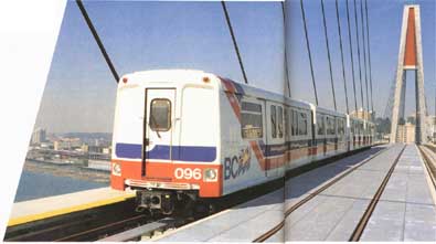
Skytrain was so called because much of the route
is over viaducts, and does full Justice to its name when passing over
the FraserRiver.
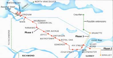
The Vancouver Skytrain Network
THE SERVICE
When Skytrain, so called because so much of the route was on viaducts, was officially opened on 11 December 1985, it was the world’s longest fully-automated Metro. VAL ( Lille) at that time had a route length of 10.4 km (6.46 miles). Both have since been extended. Full revenue- earning service commenced on 3 January 1986, in good time for Expo 86 which ran from May to October 1986.
The company formed to run the system was called the British Columbia Rapid Transit Company — BC Transit The new line, which runs from the SeaBus and railway terminal, runs to the south-east of the city, first to New Westminster —22 km (13.7 miles) — and in 1990 extended to Scott Road, which includes a new cable-stayed bridge over the Fraser River. A 4 km (2.5 mile) extension to Whalley was authorized in 1989 and completed in 1993. A further 6 km (33/4 mile) branch is proposed to serve Lougheed Mall. At present there are 16 stations. The service frequency is 3-5 minutes.
The two four-level stations on the underground section have multiple escalators and lifts. The tunnel section is 1.6 km (1 mile) long and a further 13 km are of elevated construction. The elevated sections are on lightweight, pre-stressed concrete guideways which carry normal continuously welded rails at standard 1435 mm (4 ft 81/2 in) gauge. Ground level (grade) sections are on a reserved guideway. Station platforms are 80 m (265 feet) long and over 30,000 passengers can be handled in one direction. The number of passengers handled per hour is about 8000.
TECHNICAL FEATURES
114 cars were built by UTDC. These are small by Metro standards, being 12.7 m (41 ft 9 in) long, 2.5 m (8 ft 2 in) wide and 3.1 m (10 ft 2 1/4 in) high, with twin double-sliding doors each side. Weighing only 14 tons (30,800 lb) empty, they are built of aluminum alloy and can carry 40 seated passengers and a normal standing complement of 35, increasing to 68 under crush conditions. There is also space for two wheelchairs. Track and stations have been designed to permit the introduction of longer and heavier vehicles in the future.
The Seltrac automatic train control system was provided by SEL Canada (a division of ITT) using a system developed for the Berlin U-Bahn. Typically trains are separated by time, of the order of 25 seconds, rather than distance. Allowing for station stop times, the closest sustainable headway is 75 seconds; 60-second headways can be operated but without repeatable regularity.
Whereas the VAL system employs conventional dc motors for propulsion, the ICTS is propelled and braked by a linear induction motor (see below for the definition of a Linear Induction Motor — LIM). Direct current at 600 volts is collected from two side-conductor rails — one above the other — and is converted to alternating current at variable voltage and frequency on the cars, each car having an electronic inverter which handles both power and regenerative braking. Electromagnetic track brakes of German origin are also provided. The trains have hydraulic disc-brakes, manufactured by American companies, for parking.
Like the VAL system, the trains are computer-controlled and nominally unmanned, although to discourage vandals there are roving staff, known as rapid transit attendants (RTA5). These people are trained in public information, first aid, manual driving and can handle minor technical problems such as sticking doors. They also have security, supervisory and ticket-checking responsibilities. The first train each day, while driven automatically, carries an RTA in the front vestibule ready to make an emergency manual stop in case of vandalism or if any object has fallen on the track during the three-hour shut-down period. Tickets are issued from automatic machines and must be carried and produced on demand as proof of payment.
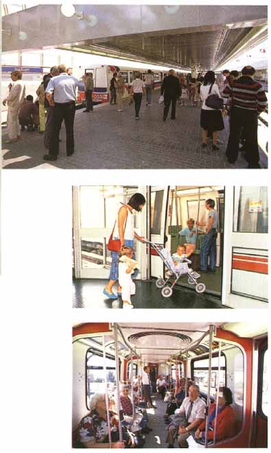 After winning the contract. UTDC, fostered support for Skytrain
by way of an intelligent public relations campaign. Five months of free
rides in the demonstration shuttle, verification of seating plans and
tests on noise levels by community groups ensured Vancouver s
cooperation.

Cutaway section of a Skytrain car. Components include: Radio antenna:
for passenger intercom, public address system, next station announcements
and data transmission to vehicle control center; power connectors: spring
applied bronze graphite shoes, located on both sides of vehicles; linear
induction motor: two per car, runs length op each truck 11 mm above lim
rail; disc parking brake: spring applied, held off hydraulically
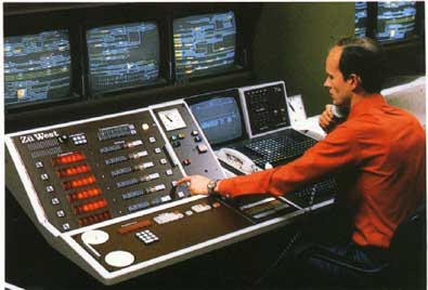
The control center, which flanks the main line in Burnaby,
is responsible for directing train movement and ensuring safe spacing
between trains. It also controls the movement of switches and enforces
track closures and speed restrictions.
LINEAR INDUCTION MOTOR
An electric motor works on magnetic attraction and repulsion. In an induction motor, the passage of an alternating current through a specially designed winding on its frame (stator) induces a reaction in another winding on the rotor, which is not electrically connected to the stator. If the stator winding is opened out flat and placed very close to a metal plate, usually of steel or aluminum, the plate will move in the same direction as the stator. If the plate is fixed and the stator winding attached to a wheeled vehicle, the vehicle will move instead.
This is the very broad principle of the linear induction motor. Its advantage is that movement of a vehicle does not rely on the friction between the wheel treads and the surface on which they are running. The disadvantage is that the motor is more difficult to control, or was before the introduction of modern electronics. Its other advantage in railway traction is its ability to absorb power and act as a brake, generating power as it does so which can be returned to the supply; this is termed regenerative braking.

Conventional Rotary Induction Motor: Stator, Rotor; Linear
Induction Motor (Lim)
SKYTRAIN ( Vancouver, Canada)
SYSTEM: Type: Gauge: Electrical system: |
Fully-automated linear-motor driven Advanced Light Rapid Transit (ALRT) 1435 mm (4ft 8 in) 600V dc side rail collection |
TRAIN FORMATION: Number of axles: |
2-car units 2X2-axle bogies per car |
BUILT: Builder: Number built: |
1985 — Metro Canada (UTDC) 114 cars |
DIMENSIONS: Length of car: Width: Height: Weight: |
25.4 in (83 ft 4 in) 12.7 m (41 ft 8 in) 2.5 in (8 ft 2½ in) 3.1 in (10 ft 2 in) 14 tons (13.75 tons) |
CAPACITY: Seated: Standing — normal: — crush-loaded: Headway: |
216 per 2-car unit 80 35 68 75 seconds, normal 60 seconds, minimum irregular |
POWER EQUIPMENT: System: |
Inverted dc, variable frequency Automatic driving |
CONTROL SYSTEM: Operating speed: |
Central computer controlled 80 km/hr (50 mph) |
TRACTION MOTORS: Number: |
Linear induction motor 1 per car |
BRAKING SYSTEM: Operative speeds: |
LIM regenerative and magnetic track brakes Regenerative to 0 km/hr |
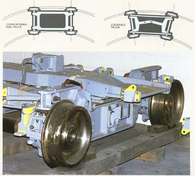
STEERING AXLE BOGIE
Usually railway coaches run on bogies in which the axles are connected to the frames through “elastic” systems in fixed positions parallel to each other. Axle spacing is usually around 2000-2750 mm (7-9 ft). On very sharp curves, the wheel flanges contact the rails at an angle, and not only do they wear each other but they also produce a lot of unpleasant noise and vibration, if the axles are allowed some freedom this wear and noise is reduced, but safety at speed is also reduced. By interconnecting the axles through two “elastic” systems, the axles can be angled on curves and the bogie “steers” through them with less wear and noise. Less wear on flanges and rails occurs at the expense of a more complicated suspension system, with more joints in the bogie mechanism.
DOCKLANDS LIGHT RAILWAY (DLR)
Like the two previous systems, the London Docklands Light Railway (DLR) was developed without many of the constraints that apply to long-established rail systems. It did have a few of its own, not least of which were severely restricted finance and a short time scale. One particular problem was the need to satisfy no fewer than three major bodies: the London Docklands Development Corporation (LDDC), the Greater London Council (GLC) and the British Government.
DLR was authorized in 1982 as a major infrastructure investment aimed at attracting industry to the former dockside areas of East London. Several proposals were examined—some involving considerable tunneling were rejected on the grounds of cost — and most included street running. It was expected that the eventual system would employ some version of the classic European three-bogie streetcar. By mid-1983 the route had crystallized to one of total segregation with no tunnels. The need to minimize the use of land together with the ability of lightweight rail to operate with steep gradients and sharp curves led ultimately to a route which made use of both of these factors and the disused track-beds of former main-line routes.
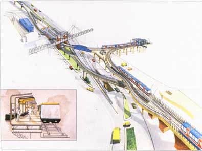
A designer’s prototype of a DLR vehicle at a station platform is
inset into an artist’s impression of the completed North Quay junction.
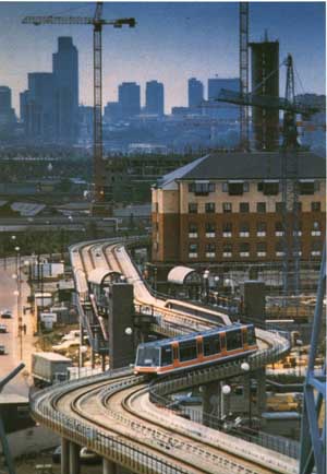
The Docklands development scheme was the flagship of Thatcher’s
Government, and was intended to attract industry to East London’s once
bustling dockside areas. The light railway was an important element in
attracting a sizeable workforce into the area.
BIDDING TO BUILD
With a maximum projected flow of only 1500 passengers per hour between the City and the Isle of Dogs, DLR was at the lower end of the light rail spectrum. In 1984 the British Government showed a preference for an all- embracing “design and construct” contract for the whole railway. Within that constraint, five consortia tendered for the contract, proposing fairly conventional 2.65 m (8ft 9 in) wide six-axle light rail vehicles. UTDC offered married pairs of four-axle cars, and Matra the complete VAL package with rubber-tired cars. The latter suffered some cost disadvantage because the trackway could not benefit from the use of existing disused trackbeds, and stations would have to have trackside screens and doors.
Eventually, from a short-list of two, the contract was awarded to the GEC-Mowlem Railway group. During the contract discussions three major decisions were taken in order to get the best passenger facilities from the very limited sum of money available:
1. trains would be automatically driven;
2. current collection would be from a third rail to avoid unsightly catenary wires (this was at the request of the LDDC);
3. full access would be provided for wheelchair passengers.
ROUTE
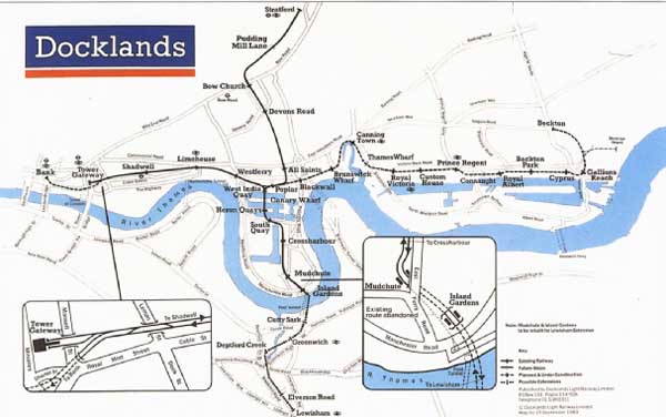
The final route begins at an elevated station close to the Tower of London, to be called Tower Gateway, and runs alongside the British Rail London-Southend line from Fenchurch Street. It then passes across an old viaduct of the former London and Blackwall Railway from Stepney Junction towards Poplar. There the line to the Isle of Dogs sweeps sharply to the south on elevated structures across the old dock basins to a station close to the river at Island Gardens ( North Greenwich). A triangular junction takes the route east for a short distance then north to Stratford, partly on the trackbed of the former North London Railway, where there is cross-platform interchange with British Railways. Trains run typically from Tower Gateway to Island Gardens and then to Stratford and vice versa.
CARS AND STAFF
Cars 28 m (92 ft 1½ in.) long were proposed by GEC Mowlem and accepted. The 11 cars have two half-bodies mounted on three bogies, and the stated carrying capacity is 227 people. Each half-body has two double inward opening plug doors, and the seating layout is a mixture of transverse and longitudinal bays. As there is normally no driver, there are forward-facing seats that give a wide view of the track ahead and behind.
The cars are based on the European three-bogie light-rail vehicles, and because there was no experience with that type of vehicle in Britain the order to build them went to Linke-Hofmann-Busch at Salzgitter in Germany. The GEC and LDDC had strong, if not always similar, views as to what was wanted and the manufacturer did well to produce a reasonable-looking vehicle which has been proved to be on the right lines with seat design, windows, general finish and lighting.
An attendant — known as a Train Captain—is carried. It is his or her duty to check tickets, help disabled passengers on and off, keep a general eye on things and finally to act as dispatcher, closing the doors and giving the starting signal to the control computer. In an emergency he or she may also drive the train from a set of driving controls in the normal position at the front of the vehide. Normally the Train Captain takes up a position at one of the inner doors.
LATER DEVELOPMENTS
DLR was opened by Queen Elizabeth II in 1987 and immediately became popular. Traffic forecasts were totally wrong from the beginning as was shown by the 50,000 passengers carried on the first public holiday of 31 August 1987 twice the level of passengers forecast for the railway in its stable post-1992 state! Not only that but a forecast of 3500 jobs on Canary Wharf had grown first to 40,000 then 60,000. To cope with this deluge the railway had to grow fast.
Even before DLR opened a necessary extension in tunnel to the Bank (Bank of England in the City of London) had been authorized. Not only that but the pessimistic traffic forecasts had been exceeded within the first year of operation, and it was clear that an upgrading was necessary. GEC-Mowlem were given the upgrading contract to lengthen stations to take two-car trains and to build a further batch of vehicles. The short time-scale inhibited the chance of making any significant changes. In particular the unsatisfactory passenger doors had to be perpetuated. The additional cars were built to Linke Hofmann-Busch license by BREL.
Because of developments of London’s docklands, the railway is being extended eastwards to Becktori and possibly even as far as Barking. There is also a proposal for a southwards extension under the River Thames through a tunnel and on to Lewisham. Work on the Beckton extension is under way, and new rolling stock has been ordered from a Belgian-British consortium.
DLR was originally conceived mostly as a showpiece and quiet light railway — something to which a government with little concern for public transport gave lip service. Now DLR is having to adapt and will become more of a light Metro. The cars will have to change into ones suited to a mass carrier without any significant loss of passenger appeal.
SPECIAL FEATURES OF DLR CARS
The new cars will have the following features:
- sliding doors
- longitudinal seats between the doors of each half-body
- passenger standing areas in doorways
- external car fault” indicators
- fault diagnosis and annunciator equipment
- ability to operate in three-car rakes in normal service and as six cars in emergency
- relocated train dispatch controls
- Category I fire rating
This indicates the position taken up by the driver if there is a breakdown of the automatic system. The fault indicator panel is to the right of the emergency door.
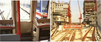
(left) This indicates the position taken up by the driver if
there is a breakdown of the automatic system. The fault indicator panel
is to the right of the emergency door. (right) Construction of the DIR
track in progress at CanaryWharf. London.
In 1990.
Next: Monorail (coming soon)
Prev: TGV
Top of Page
