The French national railway — Société National de Chemin de Per, or SNCF — has always been conscious of the importance of speed.
As soon as possible after World War II it put in hand the electrification of the line from Paris to Lyons and Marseilles, using direct current (dc) at 1500 volts. By 1952 SNCF had an Inter-City service in the 113-121 km/h (70-75 mph) average speed range. But they were not content with that.
TESTING TIMES
The start of the 1950s saw SNCF embarking on a continuous research program designed to test the speed potential of orthodox steel wheels on steel rails. By June 1954, one of their newest Co-Co electric locomotives achieved a speed of 225 km/h (140 mph) on the Paris- Lyons line near Beaune. A later test with a pair of Co-Co electric locomotives hauling a 610-tonne (600-ton) train revealed that much research was needed into the problem of maintaining consistently good current collection at high speeds. It took the best part of two decades to solve the problem.
In the spring of 1955, further tests at much higher speeds were made on the older 1 500V dc line running from Paris to the Spanish border. Two locomotives hauling lightweight trains both achieved a speed of 330.9 km/h (205.6 mph) south of Bordeaux on modified standard track and under catenaries which were of 1927 technology. While these speeds remained unbeaten for the next 26 years, the current collection problems were so severe that collectors disintegrated. The track was also severely distorted and it was clear that to achieve speeds much higher than the then normal 145-160 km/h (90- 100 mph) much work was needed on locomotive and vehicle dynamics, and on track technology. On the other hand, a speed of 320 km/h (200 mph) looked as though it should be attainable.
By the end of the 1950s, competition from Air Inter — France’s internal air service — was threatening to erode SNCF’s inter-city traffic and it was essential to reduce traveling times between cities. By 1961 a speed of 200 km/h (125 mph) had been authorized for two Capitol trains over 50 km (31.1 miles) of the Paris-Toulouse line between St Aubrais ( Orleans) and Vierzon. Here for the first time hi-tech cab signaling and automatic train control apparatus were used. A second phase of 200 km/h (125 mph) was inaugurated, but this time new rolling stock with advanced suspensions was introduced. These vehicles, known as “Grand Comfort” cars, were designed to incorporate body-tilting which was to have been fitted at a later stage.
Experience showed that the speeds did not warrant sophisticated and complicated automatic train control, and this was abandoned in favor of a change in the signaling to give advanced warning of a possible signal stop ahead. This minimized the cost of preparing two- thirds of the Paris-Bordeaux main line for 200 km/h (125 mph) running. By 1971 one trip in each direction daily was timed at an average speed of 151 km/h (93.8 mph), using conventional locomotives and rolling stock.
THE BIRTH OF TGV

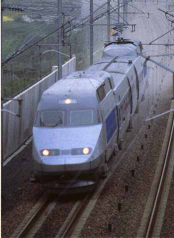
One of the first trains for the Paris-Lyon TGV line (TGV — South East) is seen traversing the typical terrain of central France. The spacing between the tracks is greater than used on “normal’ lines and helps to reduce buffeting when trains pass.
In October 1964, the Japanese launched the Shinkansen (New Railway) between Tokyo and Osaka, a distance of 515 km (320 miles) at a time when railways were struggling to establish 160 km/h (100 mph) as a standard for express trains between large centers of population (see Section 2). This event fired determination on both sides of the Atlantic for higher rail speeds, and in the summer of 1964 SNCF initiated a study of a similar high-speed railway between Paris and France’s second city, Lyons. This route was the main artery of French social and commercial life, and the main route to most of southern and south-eastern France. The existing route had a serious bottleneck in the Burgundy hills to the north of Dijon, which was also the junction for the capital’s main access to southern Switzerland and Italy.
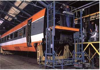
Inside the maintenance depot, special cradles are supporting a trailer car while work is being carried out. The adjacent ends of two vehicles share one bogie; such special arrangements must be made when changing bogies.
--
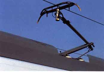
The elongated nose of TGV-E 23018 is impressive. The current collector (pantograph), located at the rear of the power roof, also supplies electricity to the power car at the other end of the train.
--
The old PLM (Paris-Lyons-Mediterranean Railway) main line was saturated and the cost of increasing its capacity by quadrupling would not be value for money because of speed constraints on the winding route. For these reasons, a new special-purpose high-speed line for passenger trains only was proposed. This line would cross central France’s vast tracts of open country and could easily be made environmentally-friendly. The new-found technology would reduce its capital cost to a fraction of that of the Japanese Shinkansen. It took a further 10 years of planning, research and development, not to mention countering opposition from ecological and road transport interests intent on thwarting the project, before construction began with the blessing of the French Government in December 1976. This was the start of the first Ligne a Grand Vitesse (LGV).
Some of the enormous cost of building a new line was avoided by using the existing main line for the first 29.9 km (18.6 miles) from Paris Gare de Lyon and rejoining it on the outskirts of Lyons. Between these points the engineering was similar to that of a motorway, but of much reduced width — it actually shares the infrastructure with two auto-routes (motorways) for a total of 71 km (44 miles). To minimize expensive earthworks, the LGV hugs the contours with gradients as steep as 1 in 28.5(3.5 per cent), close to the usual autoroute limit of 1 in 25 (4 per cent), with curvature only slightly more generous than the autoroute norm.
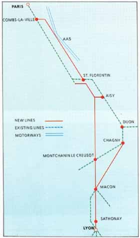
Lines of the TGV-SE
TGV trains do not employ any body-tilting mechanism but with exclusive use of the route by standard trains, the curves can be safely negotiated even at 257-270 km/h (160-170 mph). This is because the track has the ideal cant and because of the design of the low center-of- gravity, lightweight vehicles and suspension. Additionally, by sticking close to the contours, there was no need for any tunnels along the 390 km (242 miles) of new line.
The new line is very simple. There are only two inter mediate stations, at Le Creusot (Montchanin) and Macon, with three junctions in addition to those at each end. One junction feeds some TGV trains to Dijon, Switzerland and the French Alps. In addition, because TGVs are compatible with the existing system, they run beyond the limits of the new line to Montpellier, Marseilles and beyond. Since not all trains stop at the new intermediate stations, the two platforms at each are served by loops which, like the junctions with the old line, are designed to be taken at up to 220 km/h (137 mph). In addition, emergency crossovers are installed at regular intervals and sidings are provided at a number of places to hold failed trains. Even so, the number of switches is minimal.
THE TRAINS
Experience in the 1960s with gas turbine powered “Turbotrains” culminated in the reasonably successful lightweight RTG sets. Power requirements for TGV would be high, and the only prime mover that could reasonably be employed was a version of the lightweight aircraft- type gas turbine similar to those used in the RTG sets. A five-car articulated gas turbine-electric prototype train was built in 1972. During a program of prolonged trials, some 54,716 km (34,000 miles) were run at more than 200 km/h (125 mph) in the six years to the train’s retirement in 1978. By 1974, however, the oil price explosion had rendered gas turbine propulsion uneconomic, and SNCF had no option but to electrify.
One operational advantage of gas turbine propulsion was the ability to run into non-electrified territory (for example, from Lyons to Grenoble) or to use lines electrified on different systems. But now it became economic even to electrify those routes. The system chosen for TGV was single-phase ac at 25kV and a frequency of 50Hz, but as this was not compatible with the former PLM lines, electrified at 1 500V dc, the new trains would have to incur the weight penalty of having both systems. This would also give access to Marseilles and Geneva, but any extension to operation over the lines of the Swiss Federal Railways would require three-system equipment to allow operation over their lines that use 15kV ac single-phase at 16.6Hz. In the event only a handful of train sets (eight) were built with equipment to enable them to run additionally on the 15kV ac single-phase system.
REDUCING WEIGHT
To minimize weight it was decided to keep the prototype arrangement of articulation for the passenger-carrying vehicles, and the final design was an eight-car articulated unit with a two-bogie Bo-Bo power car at each end — ten vehicles in all with a tare (unladen) weight of 386 tones (380 tons). To propel this weight of train over a line with gradients as steep as 1 in 28.5 at the required average speed demands a high output from the traction motors. Accordingly, each power car carries four 525kW (720hp) dc traction motors and additionally feeds two further motors driving the wheels of the leading bogie of the adjacent passenger car, known as a “semi-motrice”.
The earlier tests showed that in order to limit the forces between vehicle and track it was necessary to minimize the total weight of the motor-bogies. Instead of the traction motors being carried in the usual way in the bogies themselves, each motor is suspended from the underside of the vehicle and drives its corresponding axle through a short Cardan-type shaft and a gearbox mounted on the bogie frame.
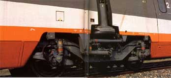
This photograph illustrates an intermediate bogie carrying the ends of two can. To ensure a good comfortable ride, both vertical and horizontal hydraulic dampers are provided. Damping is also incorporated between the two vehicle ends.
CURRENT COLLECTION
The current collector (pantograph) on the TGV-A power car must be sufficiently lightweight to follow the contact wire at the highest speeds. Current is collected by special carbon strips.
There are two pantographs, one for ac operation and one for dc. With normal operation from the 25kv line, current is fed through one pantograph specially designed for the high speeds involved. The leading power car is fed direct, while a roof-mounted 25kv line feeds the rear power car, the connection between each vehicle being made by an inductive link. When two TGV sets are coupled together, as with most trains between Paris and Lyons, the second set is also fed by one of its own pantographs, usually that on the leading power car. For operation on 1500V dc, the alternative pantographs on both power cars are used.
One of the many lessons learned from high-speed operation has been the importance of matching the performance of pantographs and the overhead system to obtain optimum performance. This must take into account the overhead line dynamics, and the need to prevent a second pantograph being affected by the disturbance in the catenary caused by the passage of the leading pantograph. The higher the speed, the more important it is that continuous contact is maintained or serious arcing occurs. Special high-speed lightweight pantographs were designed and tested on existing lines at speeds well in excess of 200 km/h (125 mph) to ensure that current collection was satisfactory.
The first series of trains, now known as TGV-E, have traction equipment with well-known thyristor control, in which the alternating current supply is regulated and rectified to supply dc traction motors. As mentioned earlier, all trains are able to accept alternating current at 25kv and 50Hz or direct current at 1 500V. Those required to run over the Swiss Federal Railways to Lausanne also have to accept single-phase alternating current at 15kV and 16.6Hz using the same transformers as for 25kV / 50Hz, but at a cost of reduced power to the traction motors. This is unimportant because speeds over the CFF/SBB (Swiss Federal Railways) are limited to 140 km/h.
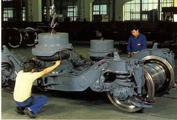
This photograph shows the secondary air springs being lowered into position. Note also the three brake discs on the nearest axle. Bogie frames must be rigid but light and great care taken in the design and manufacture. Regular inspections are made during service.
TGV-E (Sud-Est) 23000 SERIES (France)
|
GAUGE: Electrical system: |
Standard (4 ft 8½ in) 25kV ac 50hz and 1500V dc |
|
FORMATION: Power cars: Semi-motor cars: Trailers: |
2+10 2 2 6 |
|
BUILT: Builder: Number built: |
1978—86 Alsthom/Francorail-MTE/de Dietrich 109 |
|
WEIGHTS: Power car: Semi-motor car: Articulated trailer: |
Complete unit: 385 tons (378 tons) 65 tons (63.8 tons) 43 or 44 tons (42.2 or 43.2 tons) 28 tons (27.5 tons) |
|
DIMENSIONS: Power car: Semi-motor car: Articulated trailer: |
200m (658 ft 8 in) over couplers 22150mm (72 ft 8 in) 21845 mm (71 ft 8 in) 18700 mm (61 ft 4 in) |
|
SEATING: First only sets (9): |
111 First, 275 Second 287 |
|
POWER EQUIPMENT: System: |
Thyristor/Chopper ac/dc & dc/dc |
|
TRACTION MOTORS Power car: Semi-motor car: |
12X525 kW — total 6300 kW 4 2 |
|
MAX PERMITTED SPEED: Normal service speed: |
280 km/hr (174 mph) 270 km/hr (168 mph) |
|
BRAKING SYSTEM Type: |
Electro-pneumatic and rheostatic Disc and tread brakes |
THE NEWER TRAINS
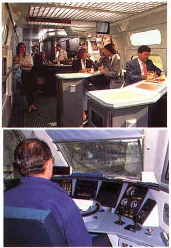
(above) Inside the cab of an early TGV-A train set the driver sits to the left of center. immediately in front of him is the control for power and normal braking. The various instruments and displays give him a continuous picture of the running conditions. (top) As wall as providing refreshments and stylish dining accommodation, the buffet car of the TG V-A features a visual display unit providing information about connecting train times and so on.
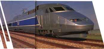
One of the trains provided for TGV-A. The styling is less ‘angular’ than that of the earlier series, and there are 10 intermediate cars between the two power cars. These trains, like their earlier counterparts, work over existing and new lines and collect current at 1500V dc as well as 25,000Vac.
Using the experience gained with the TGV-E, the new trains for the TGV-Atlantique have been changed in a number of important respects. Each set has two additional cars, giving a 2+10 formation. The original TGV power car bogies have been exceptionally successful and have been retained. The increased speed potential has been made possible because of developments in traction, aerodynamics, braking and current collection. The TGV A sets have eight ac traction motors of the self- commutating synchronous type, each with a continuous rating of 1100kw. This has been made possible by developments in electronics, to the microprocessor in particular. Traction equipment is confined to the power cars, the weight of which is slightly lower than TGV-E at 67.8 tons (66.6 tons).
The bodies of the power cars have been redesigned, with improved aerodynamic styling and a different driver’s cab layout. weight has been saved by using some parts made from aluminum or a different type of steel. Both traction and auxiliary equipment make use of the latest traction technology, such as freon-cooling, gate turn-off thyristors (GTOs), microprocessor-control electric braking, multiplexing of remote control functions, and so on.
The increased maximum speed has resulted in an improvement in braking performance. It was necessary to eliminate tread brakes to reduce maintenance cost and noise. New high-performance disc brakes have been developed, which increase the brake force by 70 per cent compared to TGV-E. This has been made possible by redesigning the discs and by the use of a microprocessor- controlled system. This latter enables the train to make full use of the available adhesion. In addition, the ac synchronous motors allow the use of a powerful electric brake independent of the power supply.
The interior design of the TGV-A incorporates a number of improvements over its predecessors. There is luxurious semi-compartment seating in first class, and second class now has fabric-covered seats and window curtains. There are two areas of seating bays which families can use, an area where young children can play, a nursery, special accommodation for the disabled, a new design of bar car and telephones. Each set has seating for 485 passengers as well as 37 fold-down seats for use in peak periods.
The speed capability was amply demonstrated on 23 September 1986, when set No. 10 attained a speed of 356 km/h (221.25 mph) on a publicity run on the LGV-E. This was of course not as high as the record made by one of the original trains in February 1981, when a speed of 380 km/h (236.2 mph) was attained. Subsequently a world record speed of 515.3 km/h (320.19 mph) was achieved near Vendôme on 18 May 1990.
Cab signaling was provided on TGV-E, and while this has been very effective, not to say essential, the system has been up-dated for TGV-A. Extra track circuit codes for the higher speed are necessary. Over the Section near Tours, which is used by “conventional” locomotive-hauled trains traveling at 160 or 200 km/h (100-125 mph), special cab displays are provided to Supplement the conventional line side signaling. Gradients on TGV-A line are less severe than TGV-E, 2.5% (1 in 40) against 3.5% (1 in 28.5) and this simplifies the signaling. Braking distances, and hence block sections, can be more or less standardized.
Of particular interest on both types of train is the electronic device fitted to the power cars which continuously monitors the line profile. When it senses a change, it adjusts the power input to the traction motors as required to maintain the speed set by the driver.
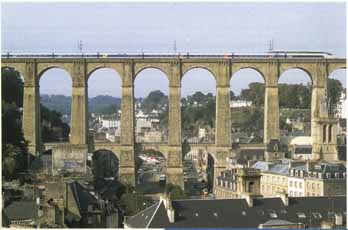
A TGV-A train passes over the rooftops along the viaduct at Morlaix in Brittany.
TGV A (Atlantique)24009 SERIES ( France)
|
GAUGE: Electrical system: |
Standard (4 ft 8 in) 25kV ac 50hz, 1500V dc |
|
FORMATION: Power cars: Trailers: |
2+10 2 10 |
|
BUILT: Builder: Number built: |
1988—91 Alsthom/de Dietrich 97 |
|
WEIGHTS: Power car: Trailer: |
Complete unit: 444 bones (436 tons) 67.8 tones (66.6 tons) 30.8 tomes (30.24 tons) |
|
DIMENSIONS: Power car: Trailer car: |
240 m (789 ft 6 in) over couplers 22 (72 ft 6½ in) 18700 mm (61 ft 4 in) |
|
SEATING: First class: Second class: |
485 116 369 |
|
POWER EQUIPMENT: Systems: |
Synchronous, hi-current ac-dc ac, dc-3ph ac |
|
TRACTION MOTORS: Power car: |
8X 1100kW — total 8800kW 4 each |
|
MAX PERMITED SPEED: Normal service speed: |
300 km/hr (186 mph) 300 km/hr (186 mph) |
|
BRAKING SYSTEM Type: |
Electro-pneumatic and regenerative; Disc and electromagnetic |
USES OF COMPUTERS
Microprocessors have a number of uses, and these are not confined to the traction control system. There are numerous procedures which are now automated which previously were done rather laboriously by hand. Practically all of the pre-departure checking (cab signaling, braking, and so on) is now done automatically. Real-time information can be provided for the driver and on-board train staff about the status of equipment. Correcting problems is easier because fault diagnosis is carried out automatically. Faults can be recorded and the conditions under which they occurred can be sent by radio to the maintenance depot while the train is moving, and many preparations can be initiated by remote radio control.
On all TGV lines a fare supplement, which includes the cost of reserving a seat, is charged. Seat reservation is recorded on a computer, and if a seat is occupied for only part of a journey, for example from Lyons to Le Creusot, it is then made available for another passenger boarding at Le Creusot to travel to Paris.
Newer High-Speed Lines
Following the success of TGV-E, plans were announced for more lines. The first would run from Paris Montparnasse to Le Mans and Tours, taking TGVs to Rennes and Brest in Brittany and Bordeaux. These would be the world’s first new lines built to carry trains at 300 km/h (186.5 mph) from the start. The French Government agreed to pay for 30 percent of the civil engineering costs of the new line, which has many tunnels and viaducts. Also in the southern suburbs of Paris, between Massy-Palaiseau and Chatillon, the line adopted the never-completed line from Paris to Chartres via Gallardon. The gradients on the TGV-Atlantique are a great deal easier than on the Lyons line, but there are more tunnels, some of them artificial —that is, the line has been deliberately buried for environmental reasons.
At Courtalain, 130 km (80.8 miles) from Paris, the line splits and the 87-km (54-mile) southern arm runs first to Vendôme, the only intermediate station. Trains for the Tours line can run through the junction at full speed. Extensive tests were made through switches at 320 km/h (199mph) on the TGV Sud-Est line before setting this standard. Trains for the Le Mans line are restricted to 220 km/h (136.7 mph). Not all trains stop at Tours, so a bypass line was built round the south of the city. It is not exclusive to TGV5 because part of the old main line was saturated, and special signaling arrangements have been made.
Like the other TGV lines, electrification is at 25kV ac single-phase except for the two ends and the Tours bypass, which use the existing 1 500V dc system. TGV5 are limited to 220 km/h (136.7 mph) over the old lines between Tours and Bordeaux.
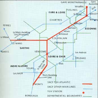 Routes of the TGV-A
The overhead gear of the TGV has been specially developed so that the pantographs can feed a continuous current to the power car. At high speeds, serious arcing occurs when contact is not maintained.
Which Traction Motor?
There are two different approaches to the use of three-phase ac traction motors. The Germans and Swiss (Brown Boveri Ltd) favored and developed the three-phase asynchronous type of motor, which has no electrical connection between the stator (frame) and the rotor. This is known as the squirrel cage motor because of the configuration of the winding on the rotor. SNCF favored the synchronous type that has a wound rotor fed through slip rings because the control circuitry is somewhat less complex.
It is this latter type which, following successful trials in an experimental set-up in a converted locomotive, has been adopted for TGV-A. The technique was first intended as the future standard SNCF practice for main-line motive power, including the 190 TGV-A power cars and 44 Sybic (Synchronous B-current) locomotives. It seems that there were many teething problems and it is now clear that the system will not be the future standard. Asynchronous traction motors will be used on the joint SNCF BR-SNCB Channel Tunnel through trains.
Equipment Layout of the TGV-A Power-Car

1 Type GPU pantograph
2 Main transformer
3 Circuit breaker, line filter
4 Traction motor control module
5 Freon cooling for semiconductors
6 Braking resistances
7 Auxiliary power supplies
8 Main compressor
9 Computer and safety equipment
10 Auto coupler
11 Crumple zone
12 High-strength structure
13 Braking controls
14 Track circuit code receivers
15 Equipment cases
16 Y230 powered bogie
17 Y237 trailer bogie
18 Baggage compartment
19 Passenger seating
20 Light alloy panels
TGV AND THE CHANNEL TUNNEL
Even before the advent of the Channel Tunnel, SNCF was considering a new TGV line from Paris to Lille. This would also form the first part of a high-speed route linking Paris with Brussels, Cologne and Amsterdam. With a Channel Tunnel there would be sufficient traffic to justify such a line. The new line, TGV-Nord, is now materializing and, unlike on the British side, will convey the very high-speed cross-channel trains to the French tunnel portal.
These new trains, the Trans Manche Super Trains (TMSTs) — discussed in detail in section 9 — have been developed from the TGVs by GEC-Alsthom. Major modifications were necessary so that the trains could suit the diverse requirements of the Belgian, French and British networks. In the area of current collection alone, British Rail has a 750V dc third-rail system, the Belgians a 3000V dc overhead system, SNCF a 1500V dc overhead system and, of course, the Channel Tunnel itself employs a 25kV ac 50Hz system. So compatibility was a key consideration.
In these early prototypes of the Channel Tunnel system, the two Outer running tunnels can be clearly seen on either side of the service tunnel. A Channel Tunnel shuttle train emerges on the left, while a service vehicle disappears on the right.