1. Electricity as a form of motive power
The evolution of various forms of motive power is well covered in Section 3 on rolling stock. Reference should be made to that section for details. Around the world during the past century there has been debate, sometimes heated and protracted and rarely conclusive, on the best form of motive power for railroads. It can be stated however that mainly railroads have changed to some form of electric motive power in recent decades and this is the current trend.

This section does not therefore address this subject again but looks at the physical, operational and management implications for railroads where electrification in some form is adopted.
Electrification is most often applied to railroads where the density of traffic movement is sufficient to justify the high fixed costs. Simply put, when there are enough trains, it is more economic to remove the power stations from the engines themselves and instead build bigger but fewer ones at stationary locations.
There is also an apparent conflict between the use of AC and DC. High voltage alternating current (AC) systems tend to have cheaper fixed equipment but more costly locomotives. Medium voltage direct current (DC) systems in contrast have more extensive and costly fixed equipment but cheaper locomotives.

Because electrification systems have developed differently on different systems, there are now several types of locomotive and multiple unit stock that are able to run on both AC and DC current. A notable example of this is the rolling stock running between Paris and London via the Channel Tunnel.
2. Generation of electricity
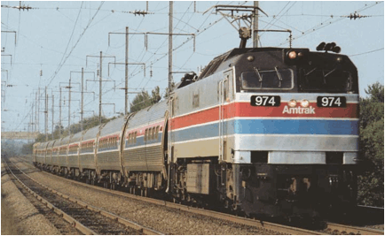
When the first railroads were electrified, generation of electricity was also in its infancy. Many railroad and tramway companies built their own generating stations to ensure that they were self sufficient. This generation was usually carried out at large steam driven installations which were often sited close to rivers for easy delivery of the large amounts of coal or coke required for firing boilers. In the U. S., the North-East Corridor (Amtrak) is an example. In London for instance, the forerunners of the Underground generated electricity at Neasden and Chelsea Creek, and the LCC Tramways had a generating station on the Thames at Greenwich. Because railroads often have high demands at peak travel times, these generating stations were not very efficient due to being over capacity for much of the traffic day. The use of electricity in homes became much more widespread between the wars and some railroad authorities gradually began to take electricity supply from the National Grid rather than rely completely on their own generating stations. The exception to this was those railroads which were mainly underground where loss of power both for traction and lighting could cause very serious life threatening problems.
In most countries now, surface railroads rely on the national supply for electrical power.
Underground railroads usually make provision for alternative supply sources, sometimes from their own generators, to cover the safety aspects, should the main supply source fail.
3. Railroad electrification systems
The two most common ways of electrifying main line railroads is by the 25 kV AC single phase system at the industrial frequency of 50 Hz or by the 750 V DC system. Metros and light railroads also use these systems but lower voltages are often adopted, particularly where some street running is involved.
Other electrification systems do exist such as 15 kV AC single phase operating at 16.6 Hz which is found in central Europe, 50 kV in Africa and some DC railroads operating with voltages up to 3,000 V. These however are far less common than the two main types described above.
At first sight, the 25 kV AC and the 750 V DC systems appear to be totally different but in fact they do have many common features. This is because, until very recently, electric trains were usually powered by 750 V DC traction motors. The electric power delivered to the trainset must therefore be suitably conditioned so that it can be applied to and used to control the speed and power output of the motor and therefore the speed and performance of the train.
On the DC system, power is taken direct from the National Grid or railroad power station at a voltage of 33 kV or 11 kV and is transformed down to a lower voltage at each sub station placed along the route of the railroad. These sub stations are usually spaced between 3 and 7 km apart and, after transforming the voltage down to a suitable level, it is rectified and supplied to the conductor rails.
On an AC system railroad however, the power is taken from the National Grid at usually 132 kV or even higher. The power is again transmitted down at each feeder station to the normal voltage of 25 kV. These feeder stations need only be spaced about 50 km apart and power is distributed around the network at this voltage by means of an overhead catenary system from which it is collected by the trainset through a sliding contact. The collected power is transformed down to a lower voltage and rectified by equipment on board the train before application to the DC traction motors.
The essential difference then between the AC and DC systems of electrification is that on the DC system, the electric power is transformed and rectified to its DC form at fixed sub stations distributed along the railroad whilst for the AC system the power is transformed and converted in a mobile, on board, sub station. For a high capacity, high density, low speed railroad with many trains spaced a few minutes apart, the DC system may well prove to be the most economic. However, for high speed, high power Intercity type trains which run less frequently, the AC system is usually found to be most cost effective.
4. The AC system connection of supply
Electrical power is provided to AC railroads at intervals between 40 and 60 km. This range of spacing generally ensures adequate voltage levels along the full length of the system under both normal and emergency feeding conditions.
Although in principle it is possible to connect railroad supply points at any voltage between 33 kV and 400 kV, the need to limit supply system disturbances usually requires connection at 132 kV or a higher voltage level.
The availability of suitable connection points and consideration of cost normally favors connection at 13 2 kV
The traction supply transformers are single-phase and on the primary side are connected between two phases of the supply authority three-phase systems. Phase pairs are chosen to minimize voltage unbalance. Where possible, the three available phase pairs should be in rotation along a route. This ensures that when a transformer is out of service, the units on either side, which are now electrically adjacent, will not be connected to the same pair of phases.
5. AC system feeder points
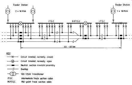
Under normal conditions each feeder station feeds to a mid-point track sectioning cabin in each direction as shown in FIG. 1 below, these being about half-way between feeder stations.
Bus-section circuit breakers are provided at the midpoint cabins which also perform an electrical sectioning and paralleling function. Further sectioning and paralleling of the railroad overhead system is provided by intermediate track sectioning cabins All British Rail 25 kV switch gear is under the control of an Electrical Control Operator. He is able, by means of a remote supervisory control and indication system, to operate all the circuit breakers, including the incoming feeder circuit breaker at feeder stations, from an Electrical Control Room which is manned continuously where the state of the network is displayed on a mimic diagram.

FIG. 1. Diagram of typical 25 kV feeding arrangement.
6. AC overhead equipment
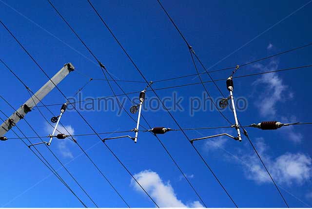
Power is supplied to the trainset by an overhead catenary system operating at a normal voltage of 25 kV. This consists of a nominally horizontal contact wire made from hard drawn copper, suspended by means of wire 'droppers' from a catenary wire cable. The catenary itself is supported on masts or portal frames spaced along the tracks at a maximum spacing of 73 m apart.
To equalize the wear of the pantograph carbons, the copper contact wire zig-zags on plan along the center of the track, the offset at each support point being 230 mm on straight track.
The height of the contact wire above rail level varies between the limits of 4.14 m and 5.94 m to accommodate minimum clearance under bridges and to satisfy statutory requirements at level crossings. Care must be taken at locations of limited clearances that no projection is allowed which might cause arcing.

FIG. 2. Modern 25 kV overhead equipment.
7. Earthing on the AC system
The current leaving the trainset first passes into the running rails of the railroad. The running rails are connected to one another and the electrification masts at regular intervals, to create a distributed earth along the railroad. This distributed earth enables current to pass from the rails into the greater mass of earth and in this way it maintains the rails close to earth potential. This limits the danger to personnel working on or about the railroad.
For the same reason, all metalwork which is exposed to touch and may become accidentally energized is also connected to the rails. Exposed metalwork may become energized due to an insulator flashover or by coming into contact with a broken energized conductor. The earthing system also ensures that, in the event of an electrical fault, the current is of sufficient magnitude to operate the protective relays of the railroad and thereby open the appropriate circuit breakers to isolate the faulty section.
8. Electrical interference
A single phase AC railroad gives rise to magnetic fields due to the flow of traction currents to and from trainsets and these fields can couple with external equipment to produce electrical interference. The major area of concern is the interference of telecommunication circuits, especially where these are parallel to the tracks. This problem is of growing importance and significance due to the explosion of interest in electrical and electronic equipment for both business and entertainment use. Railroads control the magnitude of much of the external fields by use of booster transformers which are 1:1 current transformers. These are spaced at intervals of 3.2 km along the railroad and the primary winding of the transformer is connected in series with the catenary system whilst the secondary winding is connected in series with a return conductor. Transformer action forces a current to flow in the return conductor which is equal in magnitude but which flows in the opposite direction to the catenary current. The return conductor is then connected to the rails midway between booster transformers and this has the effect of 'sucking' the return current out of the rails and earth and placing it into the return conductor. The return conductor is located close to the catenary system so that the two magnetic fields partly cancel and therefore reduce the external field generated by the railroad.
9. DC low voltage systems
In the UK, low voltage DC electrification has been adopted for many of the services of the former Southern Region of British Rail and for the whole of the London Underground. The Docklands Light Railroad in London also uses DC supply for traction.
Both BR and DLR use a single positive conductor rail at track level positioned just outside the running rails, with the running rails themselves being used for 'negative' return. London Underground however uses a positive conductor rail placed to one side of the running rails with a separate negative conductor rail running down the center of the track.
A description of conductor rails, insulators and other fastenings for both systems is included in Section 5 on Track.

FIG. 3. AC and DC distribution on a DC system.
10. AC power distribution for DC systems
DC electrification requires the provision of two separate electrical power distribution systems. An AC three-phase distribution system is required to distribute power from the national grid supply points or the railroad authority generating station to each traction sub station. At each traction, sub station located along the railroad, transformation and rectification to DC takes place and the power is then fed direct to local current rails. The AC distribution system transmits the high voltage supply to each sub station by means of a lineside cable 'main' which is continuous between two supply points. A circuit breaker is provided at each sub station for each incoming and outgoing cable and for each rectifier.
Under normal conditions, a single circuit breaker is located approximately midway between the supply points maintained in the open position and the sub station is supplied only from the nearest supply point. Under failure conditions, all sub stations can obtain power from either of the two supply points.
The design of the AC distribution system must therefore be such that the total power requirement of the sub station can be transmitted from either of the two adjacent supply points. The choice of distribution voltage depends upon this total power requirement and the distance between suitable supply points.
The use of higher voltages reduces the current drawn from the system thereby reducing power system losses and voltage reduction, allowing greater distances between supply points. However, systems at lower voltages have lower equipment costs but will either require features to compensate for voltage drops or necessitate supplies to be taken more frequently along the route.
11. DC Power distribution
Figure 3 shows the relationship between the AC and DC distribution systems on a railroad using DC traction supply.
The DC power distribution system between the sub station and the conductor rails must be designed to fulfill the following basic requirements:
To allow peak accelerating current to be taken by trains at any location.
To provide an average voltage at any train sufficient for the train timetable to be achieved.
To allow maintenance outages of equipment without affecting the ability of trains to maintain time table.
To enable the train service to be maintained under power distribution equipment failure conditions.
All DC track sections are usually double end fed from adjacent locations in order to provide the required level of security and the necessary train voltages.
All DC circuit breakers are normally maintained in the closed position.
Because of the electrical resistance of the conductor rails, it is the spacing between sub stations that dictates the voltage at the train.
The most economic DC distribution system is achieved with the greatest spacing between sub stations which will still be able to maintain the required voltage for the train. Typically sub stations are spaced at intervals along the track of not less than 4 km or more than 7 km depending upon the maximum loading in peak periods.
12. The effects of electrification
Many railroads around the world have been converted from other forms of motive power to electrification in recent decades. Trends indicate that this is likely to continue for the foreseeable future.
Experience of the effects of electrification on other engineering disciplines and operational aspects is now considerable and must not be overlooked when considering such a fundamental change.
Most of the serious effects relate to overhead AC electrification and this is the system now generally favored for modern conversion where no other system pre-exists.
Any railroad authority considering such a major change needs to address the following subjects:
Structural modifications required for over bridges to give adequate clearances.
Increased height requirements for footbridge and other parapets to provide safe protection.
Increased standards for lineside fencing to further restrict trespass, particularly if conductor rails are at ground level.
Increased protection against potential danger from cranes and other mobile plant working alongside the tracks and overhead electrical equipment.
Increased protection to staff working on or about the railroad.
The effect on other electrical equipment and systems such as track circuits, signaling, telephones, computers, CCTV etc.
13. Inspection and maintenance
As in any other part of the railroad infrastructure, maintenance of all the equipment associated with railroad electrification is essential if the service is to be properly sustained.
Each railroad authority needs to set up a separate organization to inspect and maintain all the electrical equipment, both within buildings and outside on, alongside and over the tracks. Standard electrical equipment needs to be inspected as laid down by Regulations by suitably qualified and experienced staff in that field. There are however other components which are outside the strictly electrical engineer's field and these too need specialist inspection.
Components that come under this category include the following:
- Overhead structures and catenary anchors.
- Foundations for masts/portals.
- Cable runs and their supporting structures.
- Cable ducts, troughs and sub-ways.
- Electrical bonds to conductor and running rails.
It should also be recognized that electrification brings a new dimension to all operating staff and to those whose duties require them to be about the railroad. All staff must be properly trained in relation to safe procedures that must be taken for carrying out work and in the event of accident or other incident. Apparently simple duties like cleaning signal lenses, lopping tree branches or painting station canopies, take on new risks when energized overhead electrical equipment is present.
Prev. | Next
Top of Page | Article
Index