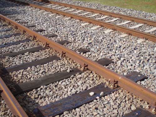
1. Origin / development of railroad track
Before the beginning of the eighteenth century, wheeled transport was generally hauled by horse and ran on surfaces which at the best was reinforced by a broken stone foundation and at the worst was simply a mud track. It was found at a very early stage of the development of land transport, that most road surfaces and foundations were very quickly damaged by heavy wagons on rigid wheels.
The first railroad tracks were laid down in the eighteenth century for horse drawn trains of wagons in collieries and quarries. These 'hauling ways' initially had a surface of stone slabs or timber baulks which proved unsatisfactory as loads grew heavier. As the Industrial Revolution progressed, the idea was developed further by adding wrought iron plates to reduce wear on the wooden baulks. This evolved further first to cast iron plates and later to edge rails, enabling for the first time the use of flanged iron wheels.
By the time locomotives came on the scene in the early nineteenth century, wrought iron rails had developed further and became strong enough to support these heavy engines without assistance from longitudinal timbers.
In 1825, the Stockton and Darlington Railroad was constructed adopting track of wrought iron rails resting in cast iron chairs supported on stone blocks set in the ground at three feet intervals. The rails were of 'T' section 15 feet long and weighed about 28 lbs per yard.
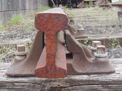
FIG. 1. Bullhead Section Rail.
As experience was gained and new technology evolved, rails steadily increased in size, both in length and cross section, and were made in steel rather than iron. Early railroads evolved the 'bullhead' or dumbbell section of rail which was standard throughout the UK up to the Second World War.
This rail was manufactured in increasing lengths and heavier sections and by the early 1900's had been generally standardized to 60 foot lengths and about 95 lbs per yard weight. Most railroads today use flat-bottomed rail.
The individual stone block sleepers were early found to be unwieldy and unsatisfactory from several points of view, largely relating to weight and the lack of tying of rails at a fixed gauge. These blocks were quickly replaced by timber cross sleepers which proved to be much more economic and satisfactory. Cross sleepers, or 'ties' as they are known in some countries, have been generally adopted world-wide and are now often manufactured in concrete or steel although timber is still used extensively. At a very early stage, the need for good preservation of softwood left in wet ballast became very obvious. By the 1880's, several railroad companies had set up their own plants to impregnate sleepers with creosote under pressure.
2. Basic components of track
Today most railroads have rolling stock with hard steel flanged wheels running on two rails set at or about 1432 mm standard gauge, supported in some way to spread loads to the ground below.
'Sub-grade' is the term used for the natural soil stratum, or embankment soil, after trimming off organic topsoil and made ground, upon which the track bed is constructed.
The 'Trackbed' comprises the ballast and any sub-ballast layers and is there to support the track, to drain water from the bottom of the sleepers and to distribute the imposed track load to such a degree that the sub-grade can resist the imposed bearing pressure adequately.
3. Track ballast
Early railroad engineers did not at first realize the important engineering function carried out by the ballast, as outlined above. Because of this all manner of material was used beneath the sleepers which today would be considered completely unsuitable. This included materials which would be cheaply and easily available locally such as ashes, chalk and clay.
Experience soon showed that good quality ballast, made of well graded gravel, crushed gravel, limestone or igneous rock was necessary if adequate foundation and good drainage is to be achieved for a reasonable period.
Today, the required depth of good quality ballast beneath sleepers varies depending upon the maximum speed of trains, the maximum axle loads carried and the gross annual tonnage expected. In general, the absolute minimum depth of ballast needed beneath sleepers for even a lightly loaded railroad should never be less than 150 mm and heavily loaded main lines can require as much as 280 mm. The currently recommended minimum thicknesses of ballast beneath sleepers for lines in the UK are as shown in FIG. 2.
To ensure both lateral and longitudinal stability of the track, particularly when using continuously welded rail, it is essential that ballast is taken up to the level of the top of the sleepers between the sleepers and given a good 'shoulder' at the sleeper ends.
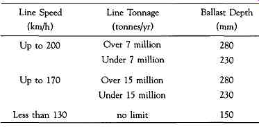
FIG. 2. Recommended ballast depths.
4. Materials for track ballast
Good quality track ballast is made from crushed natural rock with particles not larger than 50 mm or generally smaller than 28 mm. Angular stones are preferable to naturally rounded stones, to achieve the best interlock properties and resistance to longitudinal and lateral movement under dynamic loading.
If ballast particles are larger than the maximum size stated, there may only be two or three stones between the underside of the sleeper and the sub- grade will be insufficient to properly distribute the load. Too many small stones below 28 mm will however clog the ballast and reduce, in the longer term, its drainage properties. Samples of track ballast must be checked for grading by sieve analysis. Not more than 3% by weight should be retained on the 50 mm square mesh sieve and not more than 2% should pass through the 28 mm sieve.
Ballast particles can suffer degradation due to the action of traffic and maintenance operations in broadly two ways. Either edges can become rounded and lose their interlocking effect or particles can break or crush under repeated loading. Some of the softer stones suffer badly from attrition in the presence of water. This deterioration, particularly at rail joints, can be associated with 'wet spots' in the track which can cause rapid deterioration of line, level and riding comfort.
Certain tests can be introduced to check the wet attrition qualities of ballast. Generally speaking, limestones tend to have poor wet attrition qualities, crushed granite being one of the best, although expensive.
5. Sleeper functions
Sleepers and bearers or timbers (for points and crossings) need to fulfill the following basic functions:
1. Spread wheel loads to ballast
2. Hold rails to gauge and inclination
3. Transmit lateral and longitudinal forces
4. Insulate rails electrically
5. Provide a base for rail seats and fastenings
Sleepers are also often called upon to fulfill other secondary but important functions which should not be overlooked. These include:
1. Supporting wheels and/or jacks direct (in a derailment situation)
2. Acting as transverse beams when sitting on temporary 'waybeams'
3. Supporting signal engineering and other safety related equipment
4. Supporting conductor rails, electrical bonds and feeder cables
5. Reducing noise and vibration on non-ballasted bridge decks (such as trip cocks and point motors)
6. Timber sleepers
The traditional timber sleeper was accepted by most railroads as standard up to about the middle of the twentieth century, although its durability limitations were recognized.
Even today there are still many railroads using timber sleepers, where the advantages of good resilience, ease of handling, adaptability to non-standard situations or electrical insulation are very important.
Timber sleepers and bearers for surface railroads are usually made of softwood, either imported Douglas Fir or homegrown Scots Pine. The standard dimensions for softwood sleepers used in the UK are 254 mm. wide by 127 mm. thick in cross-section by 2600 mm. long.
All softwoods used in sleepers and bearers must be thoroughly seasoned and then impregnated under pressure with a suitable preservative before use. Traditionally, this preservative has been hot creosote but other materials have been used successfully in recent years which may have less associated health hazards.
Main line surface railroads are now progressively converting their important lines to prestressed concrete sleepers, which are described later.
All lines in deep tube tunnels or in locations where fire could be a risk, are provided with sleepers and pitblocks made from imported untreated hardwood such as Jarrah.
Jarrah timbers used on the surface for points and crossing work which is not protected from the weather can last up to 35 years. In the protected environment of dry tube tunnels, Jarrah sleepers on the London Underground have been known to last in excess of 50 years before needing renewal.
The author has in his possession a handsome polished jarrah pen and pencil box which bears the following interesting inscription under the lid:
'This box is made from jarrah sleepers withdrawn from the London Tube railroads after 54 years continuous service. It is estimated that during this time 500 million passengers travelled over the sleepers.' Such comment speaks for itself. Hardwood sleepers eventually usually need replacing after this long period not because the general condition of the timber has deteriorated but because it is by then not possible to get a sound fixing for chair screws.
Softwood treated sleepers on the surface can be expected to last between 15 and 25 years depending on location and traffic use. Renewal is usually required because bad splitting and/or rot has occurred.
7. Prestressed concrete sleepers (Monobloc)
As a substitute to softwood, some experimental work was carried out during the late 1930's on concrete sleepers. Originally, ordinary reinforced concrete was used but not found very satisfactory for a number of reasons. At that stage, concrete simply replaced timber, bullhead rails and cast iron chairs being used as in other conventional track.
After the Second World War, prestressed concrete was developed and used extensively on new structures. The great advantage of prestressed concrete was that concrete is kept under compression under all conditions of flexure, both under load and after. This means that tension cracks do not occur which can allow ingress of moisture and corrosion of embedded steel.
Development of prestressed sleepers took place about the same time as development of flat bottomed rail and direct fastenings.
At the time of writing, the standard sleeper for main line railroads prestressed concrete sleeper manufactured by the pre-tensioned method. In this method, the prestressing tendons are tensioned prior to the concrete being placed and are only released once the concrete has reached sufficient compressive strength to resist the induced forces thus applied. This method is also sometimes referred to as the 'Long Line' system, as sleepers are cast in long lines or beds of twenty five sleepers or more.
Some counties outside the UK adopt the post-tensioning method where tendons are placed in de-bonding sheaths and the stress is applied after the concrete has hardened by application of tensile force to the tendons by jacking and final anchoring. This method is slower but less capital intensive and lends itself to small-scale production and situations where demand is less.
Standard prestressed concrete sleepers used in the UK are normally 2515 mm long by 264 mm wide. The depth varies from 203 mm at the rail seat to 165 mm at the center line giving a total weight of 285 kg. The prestress is provided by 6 No. 9.3 mm strands for standard use increased to 8 No. strands for heavy duty. These sleepers are capable of sustaining an equivalent dynamic load of 24 tonnes at each rail seat. Allowing for impact, lurching, wheel flats, poor rail joints and etc this is equivalent to the effects of the passage of a static 25 tonnes axle.
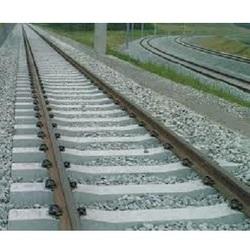
FIG. 4. Standard prestressed concrete sleepers.
Metros and light rail systems have extensively also adopted prestressed concrete sleepers. Where maximum axle loads are less than for main line as shown above, the sleeper dimensions may be reduced accordingly. However, great care must be taken in the design to ensure that adequate allowance is made for dynamic effects, particularly for both 'hogging' and 'sagging' bending moments.
The main disadvantage of the concrete sleeper over its timber predecessor is that of weight. Timber sleepers were often manhandled into their final position and replacement of single defective sleepers (or 'spotting' as it is sometimes known) was also done by hand. With concrete sleepers, some form of mechanization is required for these operations.
8. Twin block sleepers
The twin block sleeper consists of two reinforced concrete blocks joined together with a steel tie bar cast into the blocks. This type of sleeper is used extensively in Europe, particularly in France, but not in the UK. The standard sleeper weighs 230 kg which is less than the monobloc equivalent. However handling and placing can be difficult due to the tendency to twist when lifted. Twinblock sleepers can be provided with resilient 'boots' and can be incorporated into non-ballasted slab track or monolithic embedment in road surfaces for light rail street running.
9. Steel sleepers
Steel sleepers have been hardly ever used in the UK, largely because of cost and fear of corrosion in our variable weather conditions.
However, there are countries throughout the world where these sleepers are used successfully, particularly where trains run at moderate speeds only.
Reference should be made to BS 500. Most steel sleepers are inverted troughs which are either rolled to that section or rolled flat and then hot pressed to the trough shape.
Being only 68 kg in weight, these sleepers are easy to handle but the inverted trough makes them difficult to satisfactorily pack with ballast.
They have been shown to be completely satisfactory however in sidings and depots. Electrical insulation is necessary at fastenings if track circuits are being used for train detection and this is not always a simple or effective matter.
In some climates, the normal coating of mill-scale and rust is sufficient to protect against significant loss of section by corrosion. Sleepers can however be given protection by dipping in bitumen or oil during the production process.
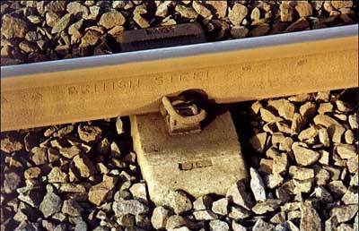
FIG. 5. Flat-Bottom (FB) rail.
10. Rail fastenings, baseplates and pads
Early railroads adopted various forms of cast iron chair which were fixed to the sleepers and in which rails sat, being held in position by hardwood wedges or 'keys'. All railroads which used bullhead section rail used fixings which were basically of this type. With the introduction of flat-bottomed rail starting in the late 1940's, a new form of fastening had to evolve.
The need was to design a resilient connection between rail and sleeper capable of resisting all forces induced by the passage of trains and by temperature and weather variations over a long period of time.
It was soon found that too rigid fixings became loose under vibration and that some degree of elasticity was necessary to resist both creep and buckling. Maintenance of the clip clamping force on the rail foot or 'toe load' was soon realised as being of crucial importance in this respect.
Since the 1940's many FB rail resilient fasteners have been designed, manufactured and used throughout the world, with varying degrees of success.
These fastenings can be grouped into three distinctive types.
These types are as follows: An elastic rail spike. This is driven into pre-drilled holes in sleepers and can be used with or without a steel or cast iron base plate.
A spring clip bearing on the foot of the rail held down by a nut and bolt element tightened to a predetermined torque. This type of fastening is still used widely in France and Germany A spring clip driven into a hole or slot in a 'shoulder' either cast into the sleeper or part of a base plate. The act of driving in the clip either twists or bends the clip thus creating a toe load on the rail.
In the UK in recent years most railroads, both main line and metro as well as some light railroads, have gone for the last type when using FB rail.
The standard fastening used by British Rail on all new FB track in recent years has been the Pandrol clip. This clip is made from circular section spring steel bar by a process which involves heating the bar, hot pressing into shape and then quenching and annealing. The majority of plain line track on BR is laid on concrete sleepers without base plates and in this case the anchorage shoulder is cast into the sleeper during manufacture.
Where Pandrol rail clips are used in conjunction with base plates the latter are secured to the timber or sleeper by chair screws.
Where DC electrified railroads have conductor rails running close to running rails, it is necessary to ensure that rail clips can be placed and maintained without potential damage or dislocation of the conductor rails.
With the Pandrol clip, this condition is satisfied as the clip is introduced into the shoulder and driven in a direction parallel to the running rail.
Some earlier spring clips were driven at right angles to the rail which certainly would not be possible close to conductor rails.
Fastenings require insulation both from electrical current and from vibration/noise. This is achieved by the introduction of resilient insulating pads at points of contact.

FIG. 6 The Pandrol Clip (center of photo).
11. Rails
All modern railroads use steel rails which are specifically rolled for the purpose from steel which has the required qualities of strength, fatigue endurance and wear and corrosion resistance. This type of steel is fully covered by British Standard Specification 11.
As has been mentioned previously, the shape of the rail has now become generally standardized as the Flat-Bottom (FB) rail. This is sometimes known as the Vignoles rail, after the inventor. British Rail have now standardized on the BS113A section rail for all important lines.
The head of the rail has an almost flat top with curves at the outer edges designed to fit the shape of the wheel tire. One of the features of a well matched rail head and wheel tire is that, when the axis of the wheel set coincides with the longitudinal axis of the track and the rail is set at its correct inclination of 1 in 20 to the vertical, the point of contact between the two is very close to the center line of the rail. This is very desirable since it minimizes the twisting effect on the rail which an eccentrically applied wheel load would produce, and by keeping the contact area away from the gauge corner, reduces both comer 'shelling' and fatigue damage.
The rail head sides slope at 1 in 20. This is to compensate for the 1 in 20 inwards slope of the rails and not only makes it simpler to check the gauge but ensures that when side wear takes place the associated gauge widening is minimized.
The thick web of the BS113A section is designed to give the rail adequate shear strength to guard against fatigue failures, particularly around fishbolt holes and under heavy axle loads at joints.
The foot of the rail is broad enough to give stability against roll-over, remembering that steering forces exerted by rolling stock produce torsional and lateral forces which have to be resisted by the rail and transmitted via the fastenings to the sleeper.
In addition to the primary function, the rail has secondary functions relating to the carrying of track circuit currents and in some cases on electrified railroads, conveying return traction currents.
Each section of rail that is used requires special steel castings, clips, bolts, resilient pads, fishplates, expansion switches etc. to make up the full structural system of the track. Most railroad authorities endeavor to keep rail types and sizes to a minimum to ensure also that maintenance stocks of replacement components can also be kept to a sensible minimum. A great deal of capital can be tied up in stock which is kept in stores just to cover an eventuality which may never happen.
There are also a number of signal related track components, like block joints, which are incorporated into the track structural system.
With third and fourth rail DC electrification systems, there are also a large number of insulators and other fittings relating to the track which are required.
Prev. | Next
Top of Page | Article
Index
