Brake and shifting cable lubrication and replacement should be given careful attention in order to maintain your bicycle in a safe and operable condition. As soon as a cable shows evidence of damage or fraying, it should be replaced, to ensure your ability to stop in an emergency.
How a Cable Works
To understand how a bicycle cable works, examine a cable in its housing. The cable is made of multi-strand steel wire, twisted together like rope. The plastic- coated housing is a spiral of steel wire like a coil spring, but with each turn tight against the next. To pull the cable out of one end of the housing, you must also push the housing back. At the far end, the cable pulls and the housing pushes. This is clear if you attach an anchor bolt (cable clamp bolt) to the far end of the cable. When the anchor bolt hits the end of the housing, you can’t pull the cable any farther out of the housing.
Now let’s look at the cable in a sidepull brake system. Just like your hands, the brake lever pulls the cable and pushes against the housing. At the brake, the cable pulls one brake arm and the housing pushes the other. If you haven’t thought about cables, you probably think that a sidepull brake applies unequal force to the two sides of the rim. In fact, the cable and housing each squeeze their brake arm against the rim with equal force.
The cable is a clever idea not only because it applies two forces, but also because it can carry forces around curves and change their direction. A cable is much simpler than any system of rods or levers that might operate a brake or shift mechanism. Imagine the Rube Goldberg lever contraption that would be needed to get from the handlebar to a rear-wheel brake!
Cable Maintenance
A cable can fail suddenly. A loose anchor bolt can slip, or the cable can fray and snap. These are good reasons to have two independent brakes, and to ser vice the cables regularly.
A cable going around a curve rubs against the inside of the housing like a rope wrapped around a tree. This creates friction. The cable must be lubricated with grease or oil to keep the friction down and to prevent rust. It’s also important to avoid sharp kinks or bends, which snag the cable.
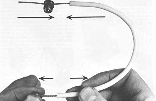
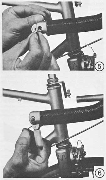
How a cable works. As you pull the cable-end button and the housing
apart, the other end of the cable and the housing are pulled together.
An unlubricated, rusty, or kinked cable works stiffly. The cable jumps along in little steps, making the brake hard to modulate. The brake may fail to release when you let go of the lever.
A drop of oil where the cable emerges from the housing is helpful between overhauls, but for a full lubrication and inspection, the cable must be removed from the housing.
The procedures that follow are essentially the same for cables of all types of tourist and hooded lever-type brakes.
To remove a brake cable on either sidepull or center- pull caliper
brakes, front or rear, first loosen the cable anchor bolt nut, and then pull
the cable out of the anchor bolt and the lower housing. Next, squeeze the brake
lever, pull the housing and ferrule back on the cable, push the cable-end button
free of the retainer slot, and then pull the cable out of the upper housing-
and-lever assembly.
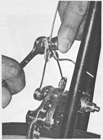
At the brake lever, insert the cable-end button through the ferrule
hole in the lever hood, then place the button in the slot at the inner side
of the brake lever.
Removing Brake Cables
Take your old cable along when purchasing a new one, to assure that it will be long enough. It’s best to replace the housing, not just the cable, especially if the old housing is kinked or bent. If the only new cable or housing you can get is too long, you can cut off the excess when you install it.
The two brakes are used differently. Most people in North America learn to operate the front brake with the left hand, but there are exceptions. Install the brake cables to suit the rider. CAUTION: Reversed cables can cause a loss of control.
Installing Brake Cables
Before installing the new cable, lay the housing along the frame in the position it will finally take. Mark the housing to cut it to length. The housing should be as short as possible while still meeting its attachment points straight-on. The shorter and straighter the cable, the more smoothly it will work. Precut cables and housings are almost always too long, because they are made for the biggest bicycles.
Cut a cable housing with a wire cutter, after removing the inner cable. Then smooth and flatten the cut end with a file. Often you can rescue a kinked cable housing by cutting off an inch or so of the damaged end—usually the end at the lever. Don’t cut the inner cable to length until you have installed it.
Apply a thick coating of multipurpose grease in the areas of the cable where it’s enclosed in the housing.
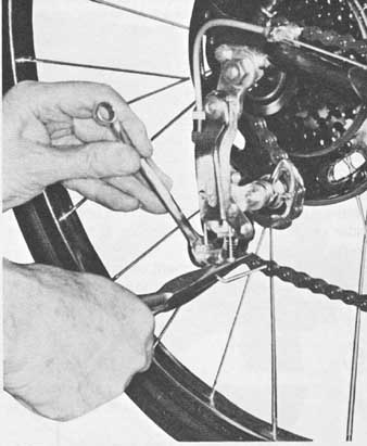
To remove the cable from either sidepull or centerpull/cantilever caliper brakes, first loosen the anchor bolt nut and then pull the cable free of the anchor bolt.
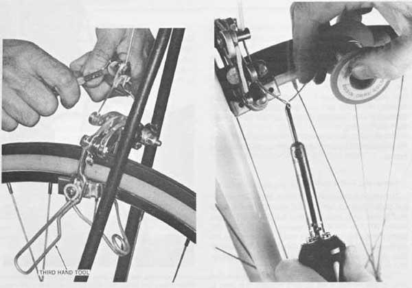
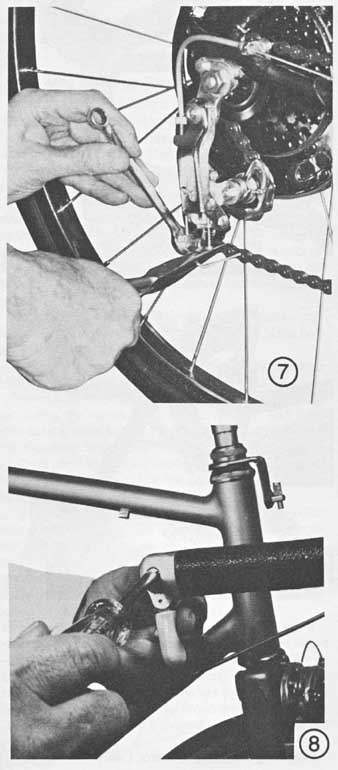
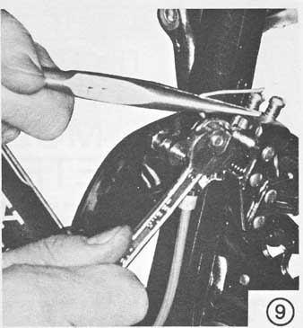
(left) After feeding the cable through the housings and anchor bolt,
clamp the brake shoes with a “third-hand” tool or a length of string or old
toestrap, pull the cable taut with a pair of pliers, and tighten the anchor
bolt nut. (right) Prevent the end of the cable from fraying by soldering together
the strands at the cut end, or else use “super glue.”
Place a drop or two of high-quality cycle oil on the cable-end button.
Push the lubricated inner cable through the ferrule and the upper housing. Leave approximately 6 inches of the cable, with the button on it, exposed from the end of the housing. Insert the cable-end button through the ferrule hole in the bracket, and then place the button in the retainer slot at the inner side of the brake lever. Pull the cable taut, and then seat the ferrule in the bracket. Slide the cable housing up against the ferrule.
Feed the free end of the cable through the lower housing and cable anchor bolt. Squeeze the brake shoes against the wheel rim, using a “third hand” tool, or tighten a piece of cord around both arms and through the wheel. Pull the cable taut with a pair of pliers and simultaneously tighten the anchor nut. Re move the “third hand” tool or piece of cord. The brake shoes should release to about 1/ inch from the rim.
Tighten the anchor bolt securely, but don’t overtighten it. You could strip the threads, or break the bolt at the hole where the cable goes through. Expect to break a few bolts before you get a feel for the correct adjustment. Oil the threads before tightening. Test that the anchor bolt is tight enough by squeezing the brake lever as hard as you can with both hands.
If the brake shoes release more than ½ inch or don’t move clear of the rim, make a final adjustment by turning the adjusting barrel. NOTE: Brake shoes will wear in use; therefore be sure to check the distance of the shoes from the rim periodically and make an adjustment if necessary.
Once the cable is installed, cut it off about 1 inch past the anchor bolt.
New bikes usually come with a plastic or metal cap over the end of the cable. This has to be removed to overhaul the cable. A more effective tactic is to apply rosin-core solder to the end of the cable, or use a drop of liquid “super glue” to cement the strands of the cable together. If the cable is of the extra-flexible braided stainless-steel type, solder won’t stick; you must use glue. If there is any grease or oil on the cable end, clean it with solvent before soldering or gluing it.
Servicing Brake Levers
A brake lever is held to the handlebar by a clamp band. On drop-bar levers, the bolt which tightens the band is inside the lever hood. You must remove the cable to get at the clamp band. By loosening a brake quick release, or by removing one brake shoe and squeezing the brake arms together, you can slip the cable out of the slot in most levers without disturbing its length adjustment.
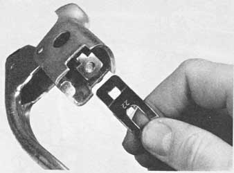
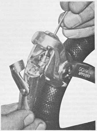
If a brake lever is secured to the handlebar by a partial clamp band,
as shown, the tabs of the nut inside the lever must face inward, away from
the handlebar.
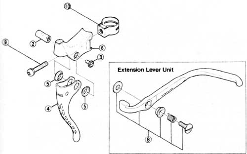
Exploded view of the Shimano model BL-Z304, a typical dropped- handlebar
brake lever.
ITEM : DESCRIPTION
2 Pull-up stud
3 LD cap
4 Main lever assembly
5 Bushing A
6 Lever bracket
8 Extension lever unit
9 Clamp screw
10 Clamp band
Most steel handlebars are 22mm in diameter and most aluminum handlebars are 23.5mm in diameter. Different-sized clamp bands are required. The size usually is marked on the clamp band.
Some clamp bands are loop-shaped, but with most levers the clamp band is U-shaped, with a hole at either end which clips to a special tabbed nut on the tightening bolt. The tabs must face away from the handlebar.
It’s very important to tighten the brake levers securely. Especially when out of the saddle, the rider may pull very hard on them. Test them by trying to twist them around the handlebars.
Rubber brake-lever hoods make the levers more comfortable and give a better grip. Slip them over the lever hoods before installing the cables. It’s easiest to install hoods from the handlebar side, before installing the brake levers.
Rubber hoods and brake extension levers get in each other’s way. Unless the handlebars are too far from the rider—a serious problem in itself—rubber hoods are preferable to extension levers. After un screwing an extension lever, you can hacksaw off the extra-long brake lever pin that holds it in place, and then install a rubber hood. This is simpler than disassembling the entire lever mechanism to install a shorter pin.
Shift-control Cables
Instructions for shift-control cables are very similar to those for brake cables. Refer to the brake-cable instructions for a description of basic maintenance procedures. This section deals with derailleur control cables; for multispeed hubs, refer to Section 14.
The most common problem with a derailleur-control cable is loosening of the adjusting wingnut on the control lever. This wingnut sets the friction to keep the lever from slipping. When the wingnut loosens, the cable slips and the derailleur shifts by itself. Some people struggle all the time in high gear because no body showed them how to adjust the wingnut while riding.
Frame and stem-mounted shift-control assemblies are almost identical, as can be seen in the two accompanying exploded views. The main difference is that the lever assembly does not have to be disassembled on the stem-mounted unit in order to re place the cable. Instead, the adjusting wingnut can be loosened.
Separate procedures are included for the fingertip controls installed in the end of the handlebars.
On bicycles equipped with front and rear derailleurs, the right-side lever must always control the rear derailleur and the left-side lever the front derailleur.
Several methods are used to mount the control cables on the frame. A solid cable housing may be used, extending from the control to the derailleur unit, held in place by one or more cable clips. Another method is to have a split housing and the fittings either welded to the frame or clamped with mounting screws.
Be sure to take your old cable with you when purchasing a new one to ensure that the new cable will be long enough.
Exploded view of a typical frame-mounted shift-control lever assembly.
Mountings differ from brand to brand—important if they are brazed to the frame.
The control levers often differ left from right. With the straight side of
the lever facing toward the frame, the buttonhole should be at the bottom.
Removing a Frame- or Stem-mounted Lever Control Cable
For a rear derailleur control cable, turn the pedals and shift the chain onto the smallest sprocket of the rear cluster and the smallest chainwheel. Move the control lever to the full-forward position. Next, loosen the cable anchor bolt nut at the rear derailleur and pull the cable and housing out of the anchor bolt and adjusting barrel. Slide the cable housing off the cable and the cable out of the fulcrum on the frame. Pull the cable out of the housing and the clips at the hanger set.
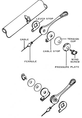
For frame-mounted control units, remove the adjusting screw at the control lever, and then remove the pressure plate, dished tension cup, cable stop, and lever from the lever stud, as shown in the accompanying exploded drawing. Remove the cable-end button from the lever.
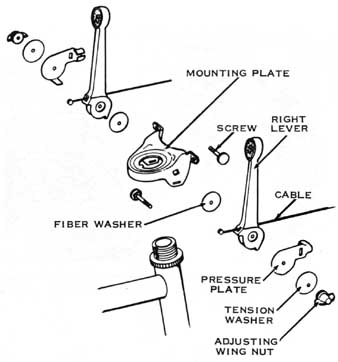
Exploded view of a typical stem-mounted shift-control lever assembly.
The hole in the lever for the control cable must always face to the rear.
For stem-mounted control units, loosen the adjusting screw and then pull the cable out through the back side of the lever.
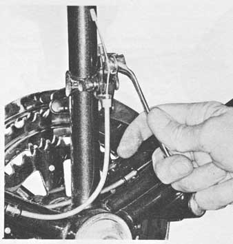
For a front derailleur control cable, loosen the cable anchor bolt nut, and then pull the cable out of the bolt and cable guide. Slide the cable housing off the cable and the cable out of the frame clip.
Remove the adjusting screw at the control lever, and then remove the pressure plate, dished tension cup, cable stop, and lever from the lever stud. Remove the cable-end button from the lever.
Installing a Frame- or Stem-mounted Lever Control Cable
Before installing a new cable, apply a thick coating of multipurpose lubricant in the areas where it’s enclosed in the cable housing. Place a drop or two of high-quality cycle oil on the cable-end button.
For frame-mounted control levers, guide the cable- end button into the button hole in the control lever. Assemble the cable stop, tension cup, pressure plate, and wing screw in the order shown in the accompanying exploded drawing.
For stem-mounted control levers, feed the lubricated cable through the back side of the lever and through the mounting bracket hole. Seat the cable-end button in the lever hole. Slide the cable through the housing and clips to the derailleur.
At the rear derailleur, position the chain onto the smallest sprocket at the rear cluster with the control lever in the full-forward position. Turn the cable- adjusting barrel down as far as it will go. Slide the cable through the barrel and the cable anchor bolt. Pull the cable taut with a pair of pliers. Check to be sure the housing is properly seated in the fulcrum and adjusting barrel. Tighten the anchor bolt nut. Cut off any excess cable, leaving approximately 1 inch beyond the anchor bolt. Solder or glue the end of the cable to keep it from fraying.
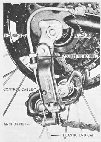
Typical control-cable hookup to the rear derailleur, showing principal
attachment points, as discussed in the text.
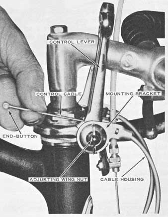
After lubricating the control cable with multipurpose grease and dripping
oil into the housing, feed the cable through the back of the lever and through
the mounting-bracket hole. Seat the cable-end button in the lever hole.
Typical front derailleur control-cable routing.
At the rear derailleur, slide the cable into the cable guide and anchor
bolt. Draw the cable taut and be sure that the cable housing is seated properly.
Tighten the anchor bolt nut securely and cut off excess cable, leaving about
1 inch beyond the anchor bolt.
At the front derailleur, guide the cable into the cable guide and anchor
bolt. Draw the cable taut and be sure that the cable housing is seated properly.
Tighten the anchor bolt nut securely and cut the cable, leaving about 1 inch
beyond the anchor bolt.
At the front derailleur, position the chain onto the smallest chainwheel with the control lever as far for ward as possible. Guide the cable into the cable guide and anchor bolt. Draw the cable taut and be sure the cable housing is seated properly. Tighten the anchor bolt nut securely. Cut off any excess cable, leaving approximately 1 inch beyond the anchor bolt, and then solder or glue the end of the cable to keep it from fraying.
Check the tension adjustment on the control lever; tighten the wingnut just enough to prevent the chain from shifting by itself. NOTE: A new cable may stretch after it has been in use. Take out the slack by turning the derailleur’s adjusting barrel.
Removing Fingertip Control Cables
Procedures for replacing a control cable for the front or rear derailleur are essentially the same, except for the work at the derailleur unit and the adjustment. The rear derailleur control must always be connected to the right-hand lever and the front derailleur control to the left-hand lever.
For the rear derailleur control cable, place the control lever in the full-forward position and then turn the pedals to allow the chain to shift onto the smallest sprocket of the cluster. Remove the cable from the cable anchor bolt and adjusting barrel. Slide the cable housing off the cable, and then remove the cable from the fulcrums or clips.
For the front derailleur control cable, loosen the cable anchor bolt and then pull the cable out of the bolt and cable guide or housing.
NOTE: The remainder of the procedures apply to both front and rear derailleur control cables.
Remove the locknut from the handlebar control lever, using the correct-size metric wrench, and then take out the lever screw. Push the lever bushing out of the mounting body, and then remove the lever and washers (on both sides of the lever) from the mounting body. Pull the cable out of the cable housing and the lever holes.
Details of other brands of fingertip levers may differ from the ones shown. On some, you remove a screw first, rather than a locknut. Many have a spring or ratchet inside the lever to pull against the cable and make shifting easier. In this case, the lever mechanism fits into a slot in the mounting body, which keeps the spring or ratchet from rotating out of position.
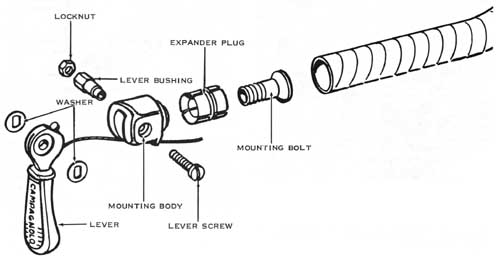
Exploded view of a typical handlebar-end control lever. The right
side and left-side lever assemblies are identical. EXPANDER PLUG; LEVER BUSHING;
LEVER SCREW
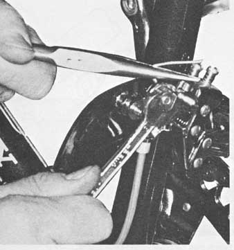
If the mounting body is to be removed in order to install new tape on the handlebars, insert the correct- size Allen wrench in the hexagonal hole of the mounting body. Turn it clockwise until the body is loose, and then pull the body out of the handlebar, as indicated in the accompanying exploded view. Remove the handle bar tape and cable housing, if it needs to be replaced.
Installing Fingertip Control Cables
[1] Position the end of the cable housing at the bottom of the handlebar
and let it extend approximately 1/8 inch past the end of the bar. Temporarily
install the mounting body in the end of the handlebar to align the end of the
housing with the mounting body’s housing stop. Secure the housing in place
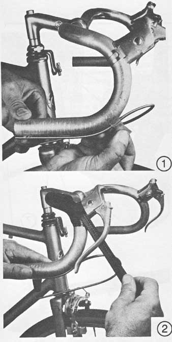
with a piece of tape. [2] Tape the handlebar, beginning about 2 inches from
the stem and overlapping each turn about one-third the width of the tape. Leave
about 2 inches of tape beyond the end of the handlebar, cut off the excess,
and then tuck the end of the tape inside the handlebar.
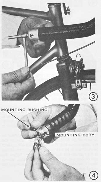
[3] Insert the control body into the handlebar, with the slotted portion
of the body facing down and the cable hole aligned with the cable housing.
Secure the body in the handlebar by turning the mounting screw inside the body
counterclockwise with the correct-size Allen wrench. [4] Place a washer on
each side of the lever, and then guide the lever into the mounting body, with
the lever key indexed with the keyway in the body. Install the mounting bushing
into the mounting body, with the flats of the bushing aligned with the flats
of the washers and the head fully seated in the hexagon hole in the body.
[5] Thread the mounting screw into the body until the lever is snug,
and then install and tighten the locknut. [6] Apply a thick coating of multipurpose
grease to a new cable in the areas where it’s enclosed within the cable housing.
Place a couple of drops of high-quality cycle oil on the cable-end button.
Place the lever in the down position, and then guide the cable through the
lever hole, cable housings, clips, and/or fulcrums to the derailleur.
[7] At the rear derailleur, position the chain onto the smallest sprocket
of the cluster with the control lever in the full-down position. If the lever
has a return spring, you will have to tighten the lever’s adjusting screw to
hold it in the down position.
Turn the derailleur’s cable-adjusting barrel down as far as it will go. Slide the cable through the barrel and the cable anchor bolt. Pull the cable taut with a pair of pliers. Check to be sure the housing is properly seated in the fulcrum and the adjusting barrel. Tighten the anchor bolt nut. Cut off any excess cable, leaving about 1 inch beyond the anchor bolt. Solder or glue the end of the cable to keep it from fraying.
[8] Check the tension on the control lever as follows. Shift the chain onto the largest sprocket at the rear cluster, and then release the lever while continuing to pedal. If the chain shifts onto one of the smaller sprockets, loosen the locknut, tighten the pivot screw until the lever action is stiff enough to prevent the chain from moving off the largest sprocket, and then retighten the locknut.
[9] At the front derailleur, rotate the cranks forward to position the
chain, and place the control lever in the down position. Draw the cable taut
with the housing properly seated. Tighten the anchor nut securely. Cut off
excess cable, leaving approximately 1 inch beyond the anchor bolt. Solder or
glue the end of the cable to keep it from fraying.
Check the adjustment of the control lever by pulling the lever back to shift the chain while you spin the crank. If the chain shifts back to the other chainwheel after the lever is released, tighten the lever wingnut or adjusting screw until the lever has just enough friction to prevent this.