1. DEFINITION AND DESCRIPTION OF THE SYSTEM
The modern tramway is a steel wheel electric train, running almost exclusively at grade along urban or suburban roads. It either shares the same infrastructure as the rest of the road traffic, or it moves on a specially built corridor or, finally, on a segregated (protected) lane, placed at one side, at two opposite sides or in the middle of the roadway.
It serves distances usually in the range of 5-20 km and it may be integrated into horizontal alignment radii as tight as 20-25 m. It is characterized by commercial speeds in the range of 15-25 km/h, and it is able to carry about 15,000 passengers/h/per direction. It commonly uses two, one-way traffic lines (double track), which are constructed either with grooved rails embedded in the pavement, or with conventional flat bottom rails.
As far as technology and operation are concerned, the modern tramway is a newer version of the conventional tram (streetcar) which monopolized the urban public transport of most cities in Europe and the United States in the early decades of the last century (Figures 1 and 2).
=======
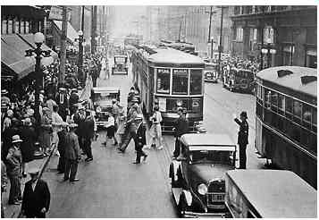
FIG. 1 Classic streetcar scene.
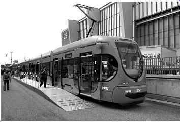
FIG. 2 Modern Tramway, Zagreb, Croatia.
=========
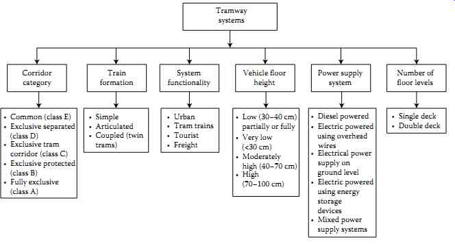
FIG. 3 Classification of tramway systems based on their different constructional
and operational characteristics.
• Common (class E)
• Simple
• Urban
• Low (30-40 cm) partially or fully
• Electrical power supply on ground level
• Diesel powered
• Single deck
Number of floor levels
Power supply system
Tramway systems
Vehicle floor height
Corridor category
Train formation
System functionality
• Double deck
• Electric powered using overhead wires
• Electric powered using energy storage devices
• Mixed power supply systems
• Very low (<30 cm)
• Moderately high (40-70 cm)
• High (70-100 cm)
• Tram trains
• Freight
• Tourist
• Articulated
• Coupled (twin trams)
• Exclusive separated (class D)
• Exclusive tram corridor (class C)
• Exclusive protected (class B)
• Fully exclusive (class A)
========
2. CLASSIFICATION OF TRAMWAY SYSTEMS
FIG. 3 summarizes the main categories in which tramway systems can be classified based on their operational and constructional characteristics.
2.1 Physical characteristics of the corridor
Tramway corridors may be classified into five different categories (classes: E, D, C, B, A).
a. Common corridor (class E): In this case, railway vehicles are mixed with road vehicles and pedestrians ( FIG. 4).
In order not to hinder the movement of road vehicles, a tram runs on special rails (grooved rails), which are properly embedded in the pavement. The implementation cost of this corridor is relatively low but the train's commercial speed remains low, similar to the commercial speed of urban buses (12-15 km/h). Furthermore, priority at traffic lights in relation to road transport cannot be given to the tram.
b. Exclusive separated corridor' (class D): In this case, grooved rails are also used, but they are separated from the general traffic by means of horizontal lining or obstacles accessible to pedestrians ( FIG. 5).
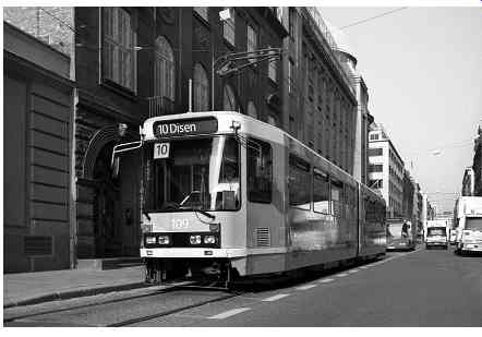
FIG. 4 Tram operation on 'common corridor' (class E), Oslo, Norway.
The tramway is, theoretically, separated from the rest of the traffic, except at level crossings. Separation of a corridor increases the commercial speed of the trains (16-22.5 km/h).
At road intersections, level crossings are maintained, however, at these locations, priority at traffic lights can be given to the tram.
c. 'Exclusive tram corridor' (class C): The existing road is used exclusively for the movement of the tram while the remaining road width is pedestrianized. The solution is applicable for narrow streets or when it is deliberately sought for sole use of the road by the tramway traffic only (for instance, in the case of commercial or historical city centers).
Grooved rails, which are embedded in the pavement, are used for the construction of the corridor, while the segregation of the tram corridor from the pedestrian area is usually achieved with the use of horizontal signaling (FIG. 6).
These three solutions deliver a relatively small improvement in the quality of service in comparison with urban buses or trolleys moving on an exclusive lane, while at the same time allowing the implementation of a tram line with a relatively low construction cost. On the contrary, the environmental impact of such an intervention is very positive.
d. 'Exclusive protected corridor' (class B): In this case, the tramway is completely separated from the circulation of road vehicles and pedestrians. The separation can be achieved by artificial or natural means (trees, plants, railings, walls, etc.), and pedestrian crossings are placed at specific intervals, depending on pedestrian flows ( FIG. 7).
Railway vehicles usually move on rails that are similar to those of classic rail tracks (Vignoles type) but are of lighter construction. However, there is always the possibility of embedding them, as in the example of FIG. 7. At intersections with roads, level crossings are maintained, but at these locations priority at traffic signals can be given to the tram.
The movement of trains occurs with no particular problems, and despite the presence of level pedestrian crossings it is possible to achieve commercial speeds of 20-25 km/h.
e. 'Fully exclusive corridor' (class A): In this case, tramway vehicles move as in the previous case (class B) on flat bottom rails, at grade, or underground, or elevated section ( FIG. 8).
The level pedestrian crossings and intersections with roads are removed so that the commercial speed reaches 30 km/h. This type of corridor is also used for the light metro and suburban rail.
The two latter solutions provide a better quality of service, but are comparatively far more expensive, especially when it is required that underground or elevated track sections are built.
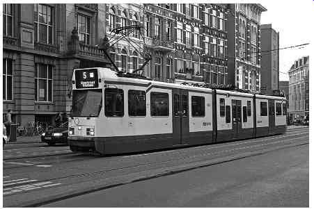
FIG. 5 Tram movement on 'exclusive separated corridor' (class D), Amsterdam,
Holland.
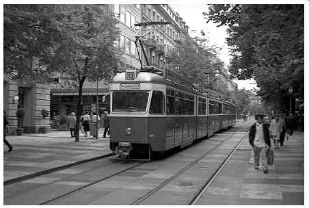
FIG. 6 Exclusive tram corridor (class C), Zurich, Switzerland.
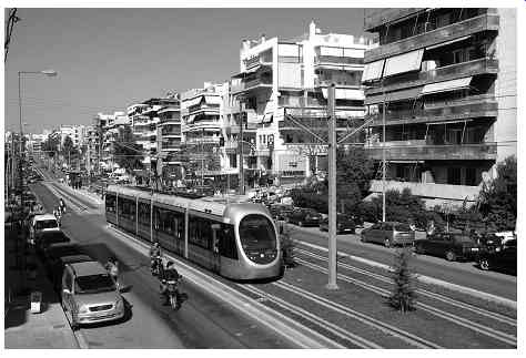
FIG. 7 Tram movement on 'exclusive protected corridor' (class B), Athens,
Greece.
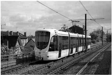
FIG. 8 Tram movement on 'fully exclusive corridor' (class A), Paris,
France.
2.2 Functional/operational criteria
On the basis of functional/operational aspects and, more specifically, based on the nature and extend of services they provide, tramway systems may be divided into four categories:
a. Urban tramways: Serve passenger movements for relatively short distances (S = 5-20 km) within an urban area; they move at low commercial speeds (Vc = 15-25 km/h).
b. Long-distance tramways (tram-trains): This technique was first applied in Germany for the Regio Citadis train at Karlsruhe (1992, 1997). Tram-trains usually serve trips that are 15-50 km long, connecting city centers to suburban and peri-urban areas.
The maximum running speed that can be developed is Vmax = 80-120 km/h, and the commercial speed is around Vc = 60 km/h.
Tram-trains are operated on infrastructure which is used not only by trams but also by other categories of railway systems (suburban, commuter and regional passenger trains, freight trains) ( FIG. 9). The vehicles are equipped, for example, with two traction systems (dual mode vehicles, diesel/750 V DC) or with dual-current systems (dual-voltage vehicles, e.g., 15 kV AC and 750 V DC), whilst the vehicle design is such that it allows trains to operate on platforms of different heights. Thus, the need to change mode is eliminated, accessibility is improved and travel times are reduced.
The length of tram - trains range between 26.50 and 37 m, the width ranges between 2.40 and 2.65 m, the height of the floor ranges between 350 and 450 mm with folding stairs and, finally, the bogies can negotiate curves of horizontal alignment radii up to Rc = 20-30 m. The average distance between stops ranges from 500 m up to 5 km.
c. Tourist tramways or cultural heritage trams: These systems serve tourist and recreational needs. They have a short connection length and move at low commercial speeds.
d. Transport of freight: Since the beginning of the twenty-first century, urban tramway systems have been used for freight. The incentive is to reduce air pollution, traffic congestion and the wear and tear of city center traffic infrastructure. Urban trams that are able to carry goods are those at Dresden ( FIG. 10), Cologne ( Germany) and Zurich (Switzerland). In Amsterdam, such trams were pilot tested, but ultimately not commissioned for revenue service.
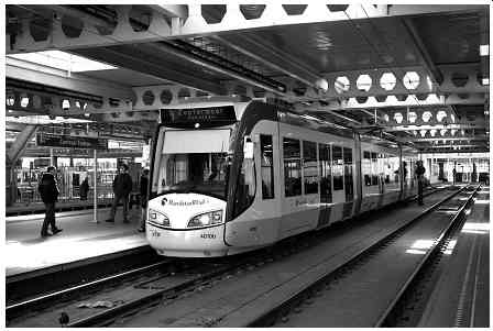
FIG. 9 Regio Citadis, Hague, The Netherlands.
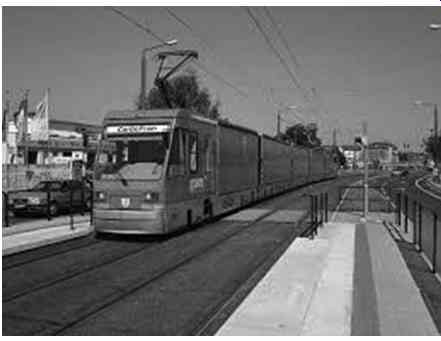
FIG. 10 Freight tram in Dresden, Germany.
2.3 Floor height of the vehicles
Depending on the distance between the floor of the vehicle and the top of the rail, tramway systems are divided into low floor, very low floor, moderately high floor and high floor.
FIG. 11 Wheelchair access at low floor tram.
=====
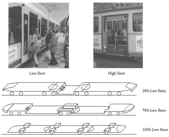
FIG. 12 Low and high floor tram.
=====
2.3.1 Low floor
The height between the rail running table and the floor of the vehicle is 30-40 cm (commonly 35 cm) resulting in passenger access to vehicles without any steps (Figures 11 and 12).
This design improves the tram's accessibility for the public, and particularly for people with disabilities, and allows for the construction of larger windows. However, it also generates some problems such as:
• Difficulty in the installation and maintenance of electrical equipment.
• Discontinuity at floor level where carriages connect to each other.
• Positioning of the equipment at the edges of the car body, thereby increasing the length of the vehicle by 10%-20%.
The minimum height of the platforms is considered to be 0.25 m. If low-floor vehicles are selected, the platforms' height can be reduced or even eliminated.
2.3.2 Very low floor
The height between the rail running table and the floor of the vehicle is <30 cm. A typical value for that height is 180 mm.
2.3.3 Moderately high floor
The height between the rail running table and the floor of the vehicle is 40-70 cm. For such trams there are stairs in order for the passengers to access the vehicle floor.
2.3.4 High floor
The height between the rail running table and the floor of the vehicle is 70-100 cm. For these trams, passengers' access to the vehicle floor is achieved by means of steps (FIG. 12).
Depending on the percentage of their length which is low floor, trams are distinguished (FIG. 12) in the following categories:
• Totally (l00%) low floor (low floor throughout the length of the vehicle)
• Partially low floor (e.g., for 70% of the vehicle length)
The technology of partially low-floor trams is old. On the contrary, the technique of low floor trams is relatively new and is now an established current state-of-the-art for the urban tram. The first vehicle of this type was manufactured as a laboratory prototype by Socimi Company in Milan in 1989. In 1990, the German company M.A.N. GHH presented the prototype of the first totally low-floor vehicle (350 mm) in Bremen.
2.4 Power supply system
On the basis of the power supply system that is used for their movement, modern tramway systems are divided into the following categories:
• Diesel-powered
• Electrically powered via overhead wires
• Trolley type
• Overhead catenary systems (single or dual-voltage, p?. 15 kV AC and 750 V DC)
• Electrical power supply at ground level
• Conventional system of third rail
• Conventional system of fourth and fifth rails
• APS (Alimentation Par Sol)
• Tramwave
• Primove (the transfer of energy to the vehicle is inductive [contactless])
• Electrical power supply, via energy storage devices (supercapacitors charged at stops via overhead wires)
• Mixed supply system
• Diesel-powered and electrically powered via overhead wires (dual mode)
• Electrically powered via overhead wires and power supply at ground level
• Electrically powered via overhead wires and energy storage devices (supercapacitors, batteries)
• Power supply at ground level, and energy storage devices (supercapacitors, batteries)
The vast majority of tramway systems are powered via the catenary system, however, the techniques that do not use overhead wires have largely developed over the last few years.
These schemes are considered to be cutting-edge technologies for rail.
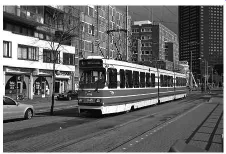
FIG. 13 Double articulated tram, Hague, The Netherlands.
2.5 Other classifications
On the basis of the formation of trains, trams may be divided into simple, articulated ( FIG. 13) and coupled (articulated or simple).
Basing on the number of levels of their floors, vehicles are distinguished as:
• Single deck
• Double deck
Double-decker trams were used extensively in Great Britain until 1950 when they were dismantled. Today, this type of tram is still in operation in Alexandria, Blackpool and Hong Kong.
Basing on the bogie's technology, modern trams are divided into those using bogies with independently rotating wheels and those using bogies of mixed behavior.
Finally, based on their construction history, urban tram systems can be divided into the following three categories:
• Category 1: This category includes new systems that were built after 1980.
• Category 2: This category includes systems that were built many years ago.
These systems were taken out of circulation and their tracks were dismantled. However, new infrastructure has recently been built for these systems and they were reopened.
• Category 3: This category includes systems that were built many years ago, and were modernized and upgraded.
3. CONSTRUCTIONAL AND OPERATIONAL CHARACTERISTICS OF THE SYSTEM
The main characteristics of tramway systems were presented in Table 6. Table 1 provides additional data on the characteristics of tramway systems. In addition, the following should also be mentioned.
3.1 Data related to track alignment and track superstructure
The cant of the outer rail at curved sections of the horizontal alignment is only deployed for the case of a fully exclusive tramway corridor (class A). For all other tramway corridor categories, the cant is avoided.

Table 1 Features and characteristic values related to tramway systems
Generally its use should be avoided in the vertical alignment radii Rv that are smaller than 150-200 m.
Basing on the tramway corridor, the track may be laid in two distinct ways:
• For the case of a 'fully exclusive corridor' (class A) and in some cases, for 'exclusive protected corridor' (Class B), the rails used are similar to those of classic railway tracks (Vignoles/flat-bottom type), but of lighter construction (46 kg/m or 50 kg/m).
For the construction of the superstructure, the excavation is usually 70 cm deep in order to ensure a unified sub-base. The track is ballasted or made on concrete (slab track). For intersections with road arteries, a special construction is foreseen.
• In the case of corridors of classes E, D, C and in many cases of B, in order not to prevent the movement of other vehicles and the crossing of pedestrians, special types of rails which are embedded in the pavement (grooved rails, FIG. 14) are used. In both cases, in order to reduce the vibrations, resilient fastenings are used, elastic pads are placed under the sleepers and antivibration layers may be employed under the ballast.
In special cases, high-damping, mass-spring systems (floating slab tracks) may be used.
These systems (see Sections 5 and 19) allow an even greater reduction of vibrations, however, they increase the implementation cost significantly.
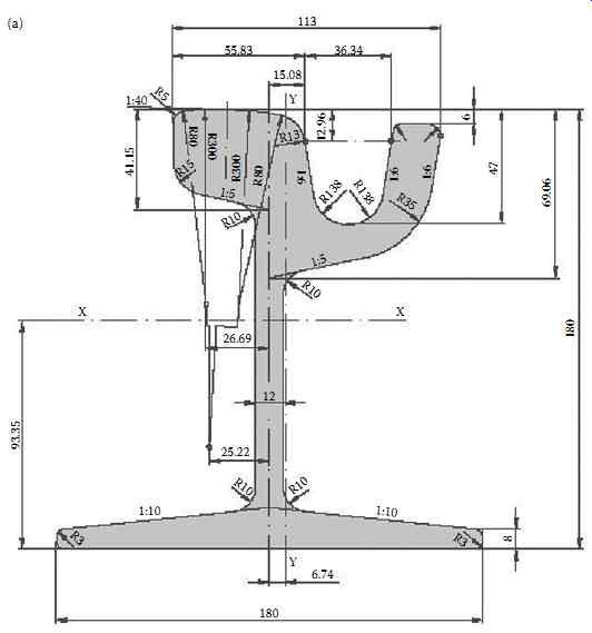
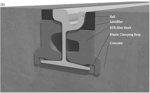
FIG. 14 (a) Grooved rail Ri60N, cross section and (b) embedded grooved
rail, sound damping system
3.2 Rolling stock data
Modern urban tramway vehicles are low floor, they feature bidirectional movement, and their frame is constructed with rounded edges in order to protect pedestrians in the event of a collision.
To improve vehicle accessibility for people with disabilities, the rolling stock manufacturers and the network operators have adopted various measures such as:
• Construction of high platforms
• General reduction of the height of the vehicle floor
• Reduction of the floor height only at the door ascending/descending spaces
• Addition of an extra car with lower floor height
The number of doors of a tram must necessarily be more than three (4-8), with a mini mum width of 70 cm in the case of a single door and 1.20 m in the case of a double door.
The height of the doors must necessarily be greater than 1.85 m. Hence, the passengers are better served at stops, and halt times are reduced (boarding-alighting time of about 20 sec).
The bogies of tramway vehicles must allow for the successful inscription of vehicles in curved track segments that have very small radii (up to 20-25 m), while at the same time they must be able to top speeds of 80-90 km/h in straight track segments (of track of good ride quality). In this context, the bogies of modern tramway vehicles are different from the bogies used in other railway systems. More specifically, two alternative technologies of bogies are currently used, namely:
• Bogies with independently rotating wheels
• Bogies with mixed behavior (they operate as conventional bogies at straight paths of the track, and as bogies with independently rotating wheels in curves)
Regardless of the bogie's technology, in order to optimize their characteristics so as to meet the track alignment geometric data, and to achieve the desired performance, manufacturers may adopt
• A small wheel base (2a = 1.70-2.00 m instead of 2.50-3.00m which is applied in conventional railway vehicles)
• A small wheel diameter (2ro = 0.60-0.70 m instead of 0.80-1.00 m which is applied in conventional railway vehicles)
The equivalent conicity of the wheels and the stiffness of the primary suspension springs constitute critical parameters of the bogies' construction for their lateral behavior.
The gradual braking (service braking) of tramway trains is usually ensured by an electric braking system (rheostat braking system equipped with energy regeneration system) which, in a second phase, is replaced by mechanical braking (brake discs, pads). The transmission is either pneumatic or electrical. The emergency braking is ensured by the additional effect of electromagnetic braking.
3.3 Tramway signaling system and traffic control
The basic principles of tram signaling systems are that (a) priority at traffic signal locations should be given to trams, and (b) at level crossings there should be collaboration between the different signaling systems intended for trams, road vehicles and pedestrians.
Regarding priority for trams at traffic lights, there are two strategies:
Passive Traffic Signal Priority: In these systems, traffic lights are set to turn green based on an average tram speed. In other words, the detection of a tram at crossings with traffic lights is not necessary. Priority is given by a standard procedure: favorable cycle time - favorable green time at each phase of the cycle time-coordination.
Active Traffic Signal Priority: In this strategy, the approaching tram sends a signal to the traffic signal controller which can change the signal, within predefined limits, in its favor. Active traffic signal priority is more effective than passive traffic signal priority, as it is based on a dynamic response to a transit request.
There are four types of active traffic signal priority systems for tramway systems:
• Dedicated priority by phasing changes
• Priority by extended green time
• Priority by phase and phase timing adjustment
• Implementation of Intelligent Transport Systems approaches
In order to locate the tram's position, two different approaches are applied: the use of Global Positioning Satellite system, or the use of special sensors which are placed on the pavement and can detect the tram as it passes over them.
The literature states that tram priority at intersections can increase the commercial speed of tram-trains by 35%.
3.4 Transport capacity of the system
The majority of tramway systems transport 150-250 passengers per train (standing and seated). In any event, the capacity of the tram, for a given acceptable passenger density (e.g., 6 passengers/m2, 4 passengers/m2), may be calculated by taking into consideration the inner length and width of the vehicle and the number of passenger seats.
FIG. 15 presents average transport system capacity values in relation to the trains' headway for four types of trams and two types of urban buses (considering aver age train/vehicle capacity values). The diagram is restricted to service frequencies between 6 and 60 trains/h. Frequencies greater than 60 trains/h cause problems to other traffic and reduce the level of service.
According to the literature, the headway of two successive trains ranges from 1.5 min up to 30 min, depending on the volume of passenger traffic, the day, and the hour of the day.
The typical values range from 5 min (peak hours) to 15 min (off-peak hours). The lowest values of train headways are recorded for the Hong Kong tram system (1.5 min during peak hours).
Regarding the passenger traffic volume, Table 2 presents the annual passenger traffic per network km for tramway systems of all European countries (ERRAC-UITP, 2009). Table 3 lists the results of statistical analysis on the annual ridership per network km in relation to a city's population.
3.5 Travel time and commercial speeds
The travel time is one of the fundamentals that determines the quality of service provided by a tramway network to its users. Low values of travel time render the tram a more attractive transportation mode and bring about a significant increase to its potential transportation volume.
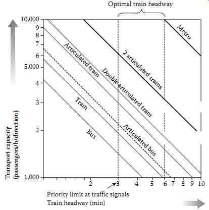
FIG. 15 Train headway - transport capacity chart for urban public transport
modes.
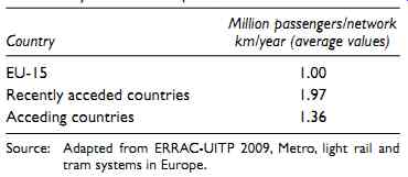
Table 2 Annual ridership per network km for tramway systems in European
countries
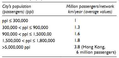
Table 3 Annual ridership per network km in relation to a city's population
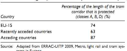
Table 4 Percentage of protected tramway corridors in Europe
The value of travel time and, consequently, the average operating speed (or otherwise commercial speed) of a tram line, depends upon various parameters, such as:
• The category of tramway corridors encountered along the route and the length per category
• The signaling system applied at level crossings with where the tram intersects with other transportation modes
• The number of intermediate stops and the distance between them
• The halt time
• The citizens' awareness of the presence of trams and their attitude
• The tram drivers' behavior
• The track alignment
• The performance of the rolling stock
• The number of level crossings
• The time of the day
The most important parameters are the category of the tramway corridor and the signal ling system used.
The proportion of the length of the tramway corridor that is protected (classes A, B, D) to the total length of the tram route is usually high and ranges between 60% (e.g., in Zurich) and 90%-100% (e.g., in Cologne, Karlsruhe). Table 4 lists the average protection percent ages for all tramway networks in Europe (ERRAC-UITP, 2009).
With regard to commercial speeds, values between Vc = 13.5-35 km/h have been recorded in practice at various low-floor tram networks, while the most usual values are between Vc = 15-25 km/h.
Table 5 lists the commercial speeds that are developed by average at all tramway networks in Europe (ERRAC-UITP, 2009).
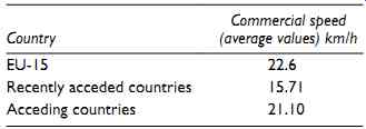
Table 5 Average commercial speed of all tramway systems of European
countries
3.6 Cost of implementing a tramway
For the assessment of the construction cost of tramway lines, the most recent urban low floor systems were selected (2012-2014 data). The power supply system, labor costs and the extent of any underground or extensive surface civil engineering works/rehabilitation are key parameters that differentiate the total implementation cost.
The urban low-floor tramway systems cost between €14 M (Palermo) up to over €60 M per track-km.
The average total cost of construction per km of an urban tramway with overhead power supply system is in the range of €20-23.5 M (€22.5 M for Europe, €20 M for Africa and €23.5 M for North America). Any special civil engineering works may significantly increase these costs (e.g., €62.8 M for the Jerusalem tram, €84.5 M for the Seattle tram).
Table 6 gives the total implementation cost per track-km for the five of the six in total in service tramway systems using mixed power supply technology (overhead catenary system + ground power supply system (APS)).
In Dubai, the APS system was applied to the total length of the network (10 km). The overall construction cost of the system reached €66.8 M per km (2014 data) due to the exclusive use of the APS, but mainly due to the high manufacturing cost of stations (indoor areas and air-conditioning).
The average cost per vehicle for an urban tram with overhead catenary system amounts in the range of €2.5 M (width 2.40 m length 32 m). This cost can reach up to €3.5 million or even more depending on the available equipment and the capabilities of the vehicle.
The average cost for an urban tram vehicle with a power supply system at ground level is approximately 15% bigger.
For tram-trains, the cost of a vehicle is significantly higher, and it approximates €4 M-€4.5 M.
Table 6 Total implementation cost of tramway systems using mixed power supply technology (overhead catenary system + ground power supply system (APS))
=========
Prev. | Next
Top of Page | Article Index