(cont. from part 1)
3. SPECIFICATIONS AND TECHNICAL SOLUTIONS FOR THE ACHIEVEMENT OF HIGH SPEEDS
3.1 Track geometry alignment characteristics
The application of high speeds automatically implies reviewing the geometry of the track alignment, and necessarily sets new values concerning the cant of track, the longitudinal slopes, the radii of curvature of the horizontal and vertical alignment, the distance between track centers and the tolerance limits for the geometric track defects.
3.1.1 Selection of horizontal alignment radii
Given that using conventional bogies it is not possible to ensure simultaneously high speeds in straight paths, and good inscription of wheelsets in curves, the horizontal alignment of the track layout should be characterized by the highest possible rate of straight paths, and by curved sections with the highest possible radii of curvature.
The selection of the horizontal alignment radii should be made based on two criteria:
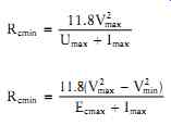
1. The 'physical' behavior of the vehicle, by applying the mathematical equations
...where Vmax, Vmin: maximum speeds, respectively, of the fastest and slowest trains that operate in the track (km/h) Umax: maximum permissible track cant (mm) Imax: maximum permissible track deficiency (mm)
Ecmax: maximum permissible track excess (mm) Rcmin: minimum curvature radius in horizontal alignment (m) ?ncmax: maximum permissible residual lateral acceleration (m/s^2 or g) 2eo: theoretical distance between the running surfaces of the right and the left wheel when centered ˜ distance between the vertical axis of symmetry of the two rails = 1,500 mm (normal gauge track)
From the results of relations (eq.2) and (eqn. 3), the higher value of Rcmin is retained.
In case that, all the trains in the network run at the same speed, only relation (eqn. 2) applies (it is taken 160 = Umax = 200 mm).
The above relations take into account:
a. The passage speed of the fastest and slowest train operating on the track
b. The categories of the operating trains (passenger, freight, etc.) and their rate of proportion
c. The behavior of the human body in lateral accelerations and ensure, for the desired speeds, the selection of values for the horizontal alignment radii that meet the lateral dynamic comfort of passengers (physical behavior of the vehicle)
By contrast, they ignore the constructional characteristics of the rolling stock that will operate on track to a great extent.
2. The 'geometric' behavior of the vehicle
Regardless of the results arising from the analytical calculation, it should be examined, mainly for speeds V = 250 km/h, whether the constructional characteristics of the bogies of the rolling stock which are going to circulate on the track allow, for the specific radii of curvature, the proper inscription of the vehicle bogies.
Specifically, if the bogies are characterized as too stiff on the level of the primary suspension (e.g., longitudinal and transversal stiffness Kx, Ky > 107 N/m, see section 3), then the value of the horizontal alignment radius, which was calculated analytically, should increase by a rate.

TABLE 1 Selection of horizontal alignment radii on high-speed tracks
TABLE 1 displays indicatively for:
a. Vmax = 300 km/h, Umax = 180 mm, ?ncmax = 0.2/0.5/0.7 m/s2, Ky = 107 N/m.
b. And for various values of the longitudinal stiffness Kx of the primary suspension of vehicles.
i. The theoretically minimum horizontal alignment radius Rco, which ensures the inscription of bogies without wheel-flange contact, and without wheel slip page. This value arises from the application of simulation models that describe the lateral behavior of railway vehicles.
ii. The minimum horizontal alignment radius Rcmin that arises from the application of mathematical equation (eqn. 2) and which does not take into account the stiffness of the primary suspension.
iii. The % rate by which the value of the above radius Rcmin should be increased, for the value Rco to arise, emerging from the application of simulation models.
At this point, it should be highlighted that the final rate of increment depends on the landscape and on any impact of the track layout on the surroundings built environment.
3.1.2 Distance between track centers
In high-speed networks, regardless of the traffic load, a double track is exclusively used for safety reasons. The track gauge is normal or broad.
In networks of track design speeds at Vd = 200 km/h, the minimum distance between track centers is set at ? = 4.20 m.
In networks of track design speeds at Vd = 300 km/h, the minimum distance between track centers is set at ? = 5.00 m.
The increase of the distance between track centers at these speeds is imposed due to the intensification of the aerodynamic effects in the event of crossing of trains travelling in opposite directions.
3.1.3 Longitudinal slopes
In the case of operation of exclusively passenger trains, due to lower axle load, lighter trains and electrification, high longitudinal slopes, in the region of i = 3%-4%, may be applied.
The adoption of high longitudinal slopes limits the extent of the civil engineering structures.
3.2 Track superstructure components
The better ride quality of the track superstructure allows the reduction of the vertical dynamic stresses, ensuring a smoother rolling of the trains and better track robustness. The systematic operation of high-speed trains, as well as the numerous tests, confirmed the following:
• Use, throughout the network, of exclusively continuous welded rails (CWR)
• Fixing of sleepers/rails, assisted by exclusively double elastic fastenings and the use of heavy rails of UIC 60 type (60 kg/m)
• Use of concrete sleepers (monoblock or twin-block sleepers)
• Adoption of ballast width of 30-35 cm with high-hardness filling materials or, alter natively, the adoption of slab track
• Homogenization of track stiffness characteristics
With regard to crossings, the use of swing nose crossings with a movable point frog ( FIG. 2) is required. This technology offers the possibility of high-speed passage, both at the main branch and at the diverging branch of a junction.
3.3 Civil engineering structures
3.3.1 Tunnel traffic
The reduction of the aerodynamic impacts that emerge in a tunnel is achieved by reducing the ratio...
where...
Sc the affected cross-sectional surface of the train Su the area of the useful cross section of the tunnel ( FIG. 3) This ratio is called 'blockage ratio drag coefficient' of the train in the tunnel, and:
• For single-track tunnels it is considered equal to 0.30-0.50
• For double-track tunnels it is considered equal to 0.14
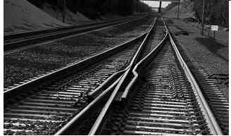
FIG. 2 Movable point frog in a junction area.

FIG. 3 Cross sections of railway tunnels: (a) excavated, (b) effective,
and (c) useful.
TABLE 2 displays the required area of the useful cross section Su in relation to passage speed Vp in a double-track tunnel, for the cross section of the frontal surface of the vehicle, of approximately Sc = 10 m².
The increase of the useful cross section reduces all the aerodynamic impacts mentioned in Section 2.
• Operation exclusively of trains with airtight car-body structure: The use of special trains reduces the annoyance of passengers from the fluctuation in pressures exerted frontally and laterally on the train.
• Adopting a twin-bore tunnel instead of a single-bore double-track tunnel: With twin tunnels, the crossing of trains travelling in opposite directions is prevented, resulting in the reduction of waves from outer pressures that may cause problems to the passengers, the rolling stock and the freight.
• Specially shaping the tunnel inlets ( FIG. 4): With this shaping, the 'tunnel boom' effect is reduced. The area of the lateral cross section of an entrance is usually 1.4 times greater than that of the lateral cross section of the tunnel.

TABLE 2 Required useful cross section Su of a double-track tunnel for
high speeds
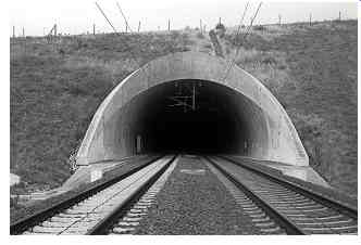
FIG. 4 High-speed tunnel entrance, Reisberg Tunnel, Germany.
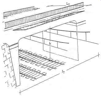
FIG. 5 Passage of an electrified railway track under a road bridge
- height clearance h, civil engineering structure width LT, and civil
engineering structure length l T. (Figure based on SNCF 1984, Ligne aérienne
de traction électrique en courant alternatif monophasé 25 KV-50 Hz, Internal
document, Paris.)
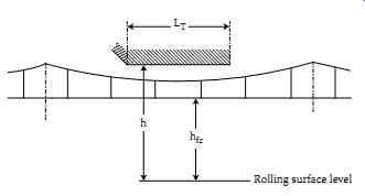
FIG. 6 Civil engineering structures of small width (LT = 20 m) - free
passage of catenary. (Figure based on SNCF 1984, Ligne aérienne de traction
électrique en courant alternatif monophasé 25 KV-50 Hz, Internal document,
Paris.)
3.3.2 Passage under bridges
The operation of trains at very high speeds requires special handling, with regard to the selection of the height clearance h of the rolling surface of the rails from the lower surface of the bridge carrier ( FIG. 5).
This distance, in an electrified railway line, also depends, among other things, on the train passage speed. The lifting of the contact wire, for speeds in the region of 230-300 km/h, may take values in the region of 12 cm at the catenary support points, and slightly greater in the middle of the opening.
In the case that the civil engineering structure is of small width (LT = 20 m), the installation of the catenary is performed by free passage, and the civil engineering structure is centered in the middle of the catenary opening for the best possible utilization of the available height ( FIG. 6).
TABLE 3 provides the values of height clearance h, for passage speeds Vp = 250 km/h, for various widths of civil engineering structures LT and for various heights of the catenary contact wire hfc, with hfc = 5.20-5.75 m.
For the drafting of TABLE 3, it was assumed that
ho = 0.10 m, Chmin = 0.555 m, I1 = 0.48 m.
where
ho: track uplifting following maintenance works
Chmin: constructional height in the middle of the catenary opening I1: isolation distance of wire-grounded structures
As can be seen from TABLE 3, in cases of railway track passage under civil engineering structures with width LT > 35 m, the required height clearance h increases steeply.
Under these conditions, for reasons of economy of the construction, in cases of civil
engineering structures of large width, another method may be adopted for their installation (FIG. 7).
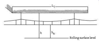
FIG. 7 Civil engineering structures of large width - catenary fixing
exclusively under the civil engineering structures. (Figure based on
SNCF 1984, Ligne aérienne de traction électrique en courant alternatif
monophasé 25 KV-50 Hz, Internal document, Paris.)
3.3.3 Track fencing
In high-speed networks, fencing on each side of the track is compulsory throughout the track. This aims ( FIG. 8)
• To reduce the likelihood of accidents which involve railway vehicles and pedestrians or animals (run-offs)
• To protect fauna and particularly larger mammals
3.3.4 Noise barriers
On the sides of the line, mainly in inhabited areas, noise-protection walls are constructed, specially designed in order to prevent noise transmission effects ( FIG. 9) (Rechtsanwalt et al., 2002).
The basic difference, compared with the noise barriers placed in highways, is due to the impact - upon train passage - of pressure-sub-pressure waves on the noise barriers, which should be taken seriously into account in dimensioning (Rechtsanwalt et al., 2002; Schweizer Norm. SN 671 250a, 2002).

TABLE 3 Height clearances of an electrified railway line - civil engineering
structure deck for various values of LT and hfc - passage speed Vp =
250 km/h - free catenary passage
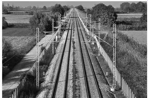
FIG. 8 Railway line with wire fencing on both sides, Rapsani, Greece.
The size of this impact depends mainly on:
• The square of speed of the passing train
• The aerodynamic shape of the train
• The shape-figure of the noise barrier
• The distance of the noise barrier from the track center
A uniform load q is considered as a characteristic value of the impact of the pressure- sub-pressure wave, the value of which is given in FIG. 10 in relation to the distance of the noise barrier from the track centre and for different speeds. For speed V = 300 km/h and lateral distance ad = 2.30 m from the track centre, the maximum value of q is observed (q = 1.8 kN/m^2) (Schweizer Norm. SN 671 250a, 2002).
Then the values of q that arise from the diagram of FIG. 10 increase or decrease by a coefficient K or K' depending on the type of the rolling stock and the dimensions of the noise barrier (TABLE 4).
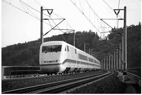
FIG. 9 Concrete noise barriers, Aula Bridge, Germany.
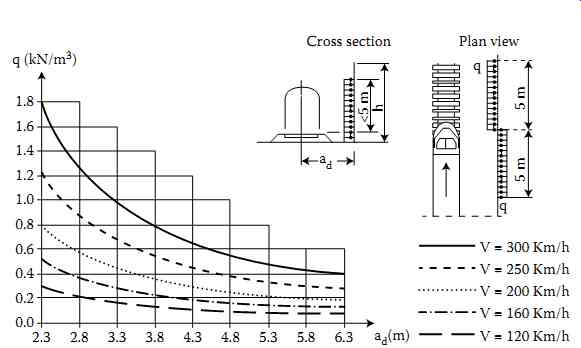
FIG. 10 Change of the uniform load q in relation to the lateral distance
ad of the noise barrier from the track centre for different speeds. (Adapted
from Schweizer Norm. SN 671 250a. 2002, Schweizerischer Verband der Strassen
- und Verkehrsfachleute (VSS), May.)
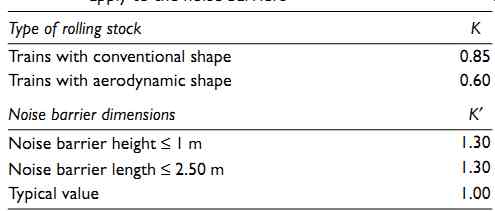
TABLE 4 Values of the coefficients K and K' for decrease and increase,
respectively, of the aerodynamic load that apply to the noise barriers.
3.3.5 Handling aerodynamic effects in an 'open' track and on platforms
With respect to the 'open' track, the problems are handled through the aerodynamic design of trains, the increase of the distance between track centers and the placement of special protective walls and longitudinal noise barriers along the track.
With regard to the platforms, the problems are handled with the reduction of the train- passage speed in the station areas, the observance by the passengers and the staff on platforms, of a minimum permissible distance from the tracks and the installation of ventilation ducts on platforms.
3.4 Track systems
In high-speed networks, the signaling system should provide for, at least in the sections where speeds of more than 220 km/h are developed, the ability to receive signals in the driver's cab. This signal is attained through special frequencies, which, through the track,
transmits to special screens placed in the driver's cab, the current or the forthcoming indication to be observed. Thus, the train drivers receive, either on a permanent basis or instantly, information about the permissible speeds in various block sections.
A measure to reduce the likelihood of accidents in a high-speed network is the absence of railway level crossings.
3.5 Rolling stock
Interventions to the rolling stock concern mainly the aerodynamic design of vehicles, the design of bogies, the braking system and the dimensioning and construction of their frame.
3.5.1 Aerodynamic design of vehicles
3.5.1.1 Reduction of the coefficient K1
The aerodynamic resistances Wa of the trains are given by the mathematical equation

(eqn. 4)
where K1: a parameter that depends on the shape of the 'nose' and the 'tail' of the train Sc: the lateral cross section of the affected surface of the train Ltr: the train length p: the perimeter that encloses the rolling stock laterally, up to rail level (rolling stock outline) K2: a parameter that depends on the construction of surface p · Ltr The reduction of coefficient K1 allows the reduction of coefficient Cw, and as result, the reduction of the aerodynamic resistances.
The finite element method is the most suitable for the design of the aerodynamics of vehicles. It enables the application of air flow forces to every part of the vehicle, resulting in the shape of the vehicle that favors the development of high speeds, and minimizes energy consumption.
3.5.1.2 Reduction of coefficient K2
The diagram of FIG. 1 lists all the constructional parameters of a vehicle that affect the aerodynamic resistances of a train, as well as the rate of contribution of each of them to the value of coefficient Cw. The shape of the 'nose' and the 'tail' of the train are directly related to the value of coefficient K1, while all the other parameters concern coefficient K2.
The use of trains with shared bogie vehicles is increasingly adopted. These fixed formation trains are equipped with special type bogies (Jakob-type bogies). In these trains, two vehicles are successively straddled on each 2-axle bogie, thereby reducing the number of bogies to nb/2 + 1 (where nb is the original number of bogies), and hence, the gap between the coupling of the vehicles, as well as the total weight of the train ( FIG. 11).
All the above conditions allow a significant reduction of coefficient K2 and, hence, of the aerodynamic resistances.
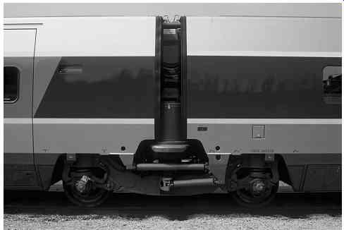
FIG. 11 Articulated train formation with shared bogie vehicles, TGV-ATLANTIQUE,
bogie Y-237.
3.5.2 Design of bogies
Vehicles intended to move at very high speeds are equipped, in their vast majority, with conventional bogies (see Section 3.2.1). Given that with this type of bogies it is not possible to attain simultaneously high speeds in straight paths and good inscription of wheelsets in curves, a large percentage of the network's length is constructed in straight path, and the constructional parameters of the vehicle are optimized, in order to ensure high speeds in straight paths (see Section 3.3).
At the same time:
• The profile of the wheel treads is fixed in frequent intervals (every 300,000 km), so that their initial conicity is maintained.
• The static axle load is reduced to 16-17 t.
• The unsuspended and semi-suspended masses (wheelsets, bogies) are reduced.
3.5.3 Braking system
Safe braking at high speeds is attained by combining various braking systems and devices, such as disc brakes made of specially processed steel, rheostatic braking, electromagnetic shoes and anti-lock braking system (wheel slide protection).
3.5.4 Vehicle design: Construction
From the conception of the idea of high-speed trains, the engineers' choices were guided by caution. The dimensioning of the rolling stock and the track is performed with high safety considerations. The durability of the framework of the vehicles is increased, and the bumpers of the leading vehicle are strengthened. At the same time, a series of auxiliary devices and automations ensure the smooth movement of the train in case of failure of specific functions, and warns the train drivers of potential problems.
3.5.5 Implementation cost
The infrastructure cost of a high-speed, double-track line varies from €10 to €40 M per track-km. It depends on the percentage of line length constructed with slab track, the length of civil engineering structures (tunnels, bridges) and the difficulty of the topographic relief.
4. HISTORICAL REVIEW AND CURRENT SITUATION OF HIGH-SPEED NETWORKS AND TRAINS
The application of high-speed networks began in Japan in 1964 with the operation of the Shinkansen train in the Tokyo-Osaka line (maximum running speeds Vmax = 210 km/h, connection length S = 515 km).
In Europe, the operation of high-speed trains began in the early 1980s. The French rail ways were the first to operate high-speed trains in their network. Specifically, in the autumn of 1981, the TGV Paris Sud-Est train was routed in the Paris-Lyon new line, originally with a maximum running speed of Vmax = 260 km/h which was increased (from 1983) to Vmax = 270 km/h. It was followed, in the autumn of 1989, by the TGV Atlantique train, which was routed with Vmax = 300 km/h on the homonymous corridor, serving areas in the western and southwestern France.
Today, the technical developments in the field of the rolling stock, as well as in the field of the track, allow a railway train to move in complete safety, in a straight path of good ride quality, at speeds of 350 km/h.
The operation of high-speed trains today occurs either in new lines with high-speed specifications or in upgraded existing tracks. In both cases, the trains use conventional or tilting technology.
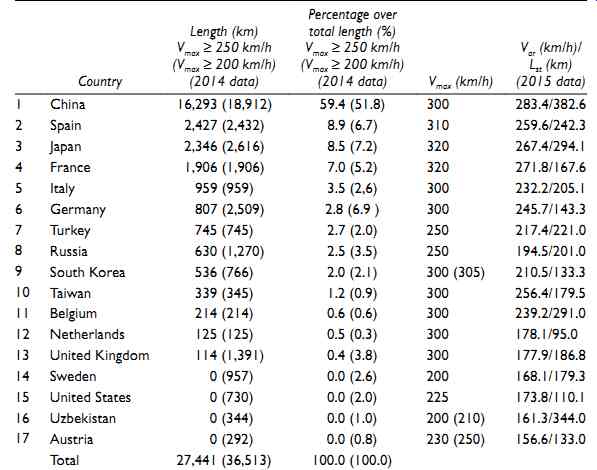
TABLE 5 Summarized data for high-speed railway networks
TABLE 5 provides a summary of statistics on high-speed rail networks.
The data recorded and analyzed in the following relate to the year 2014 for the length of the lines and 2015 for the speeds. The raw data were obtained both per country and per line, from various available sources and cross-checked. Afterwards they were further manipulated for the needs of this section.
The total length of lines where the developed running speeds Vmax are greater than 250 km/h amounts to 27,441 km in the world. China has the longest lines (S = 16,293 km) holding a percentage of 59.4%, followed by Spain (S = 2,427 km, 8.9%), Japan (S = 2,346 km, 8.5%) and France (S = 1,905 km, 7.0%).
Moreover, China has the greatest length of lines where the developed running speeds Vmax are greater than 200 km/h (S = 18,912 km, share 51.8%) in the world.
TABLE 6 provides the high-speed railway lines per country, their length, the year in which they commenced operation and the maximum running speed that can be developed (UIC, 2014b; Wikipedia, 2015b).
TABLE 7 displays the basic constructional and operational characteristics of high-speed trains (without tilting car body) that operate currently in new and upgraded high-speed tracks worldwide.
TABLE 8 displays the basic constructional and operational characteristics of high-speed trains (without tilting car body) which are going to operate in the coming years.
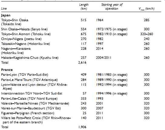
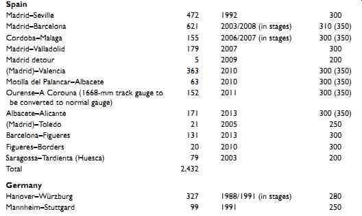
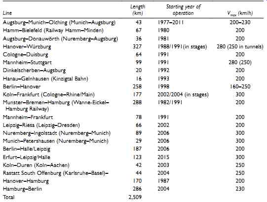
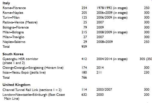
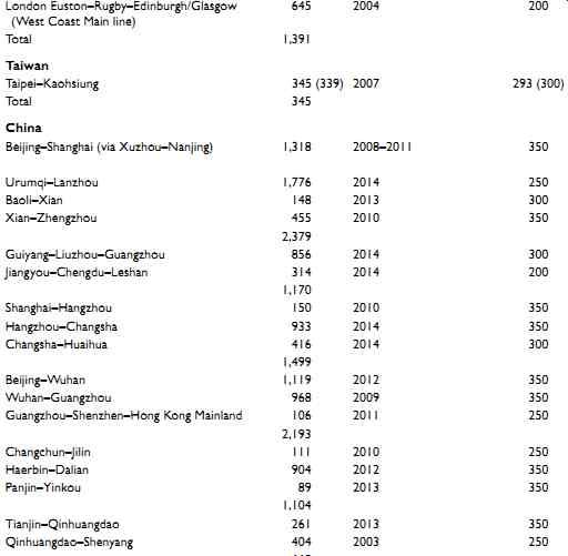
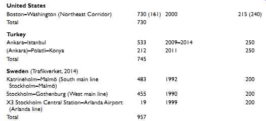
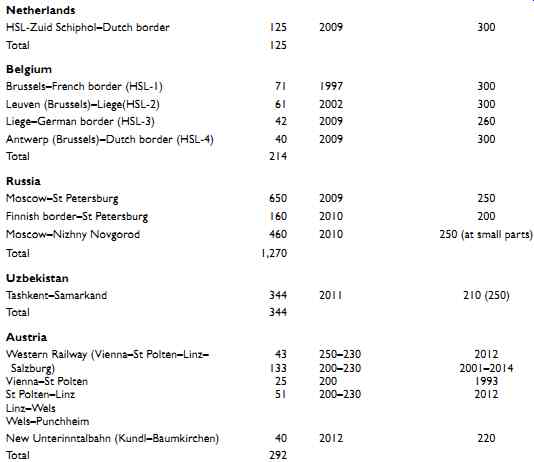
TABLE 6 High-speed railway lines per country
5. INTEROPERABILITY ISSUES
The term 'railway interoperability' implies the capacity of the trans-European railway sys tem to allow safe and continuous circulation of trains among its various segments, achieving the required performance in specific lines. This capacity is ensured by a set of regulatory, technical and operational requirements which must be satisfied. These requirements were set by Directive 96/48 which also established the above definition.
The railway interoperability concerns two different cases of railway operation:
• High-speed networks and specifically the operation of trains in the categories of tracks (I, II, III) as they were defined in Section 1.
• Conventional-speed networks: The conventional-speed networks include new tracks which are designed for speeds less than 200 km/h or for existing tracks which are upgraded. However, the track design speeds remain less than 200 km/h.
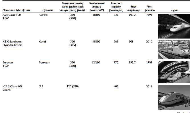
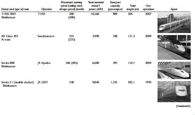
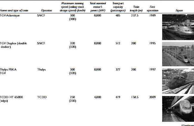
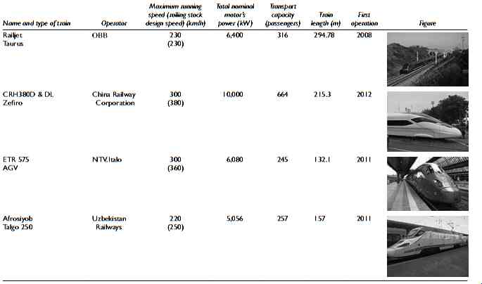
TABLE 7 High-speed conventional technology trains worldwide (indicative
table)
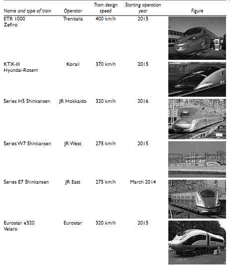
TABLE 8 High-speed conventional technology trains that are going to
get into circulation in the coming years
In order for the trans-European network to be implemented, the railway interoperability required the high-speed railway system to be analyzed in subsystems. These subsystems are described in detail in Annex II of Directive 96/48 and they are the following:
• Infrastructure
• Rolling stock
• Energy
• Control - command and signaling
• Operation and traffic management
• Maintenance
• Telematic applications for passenger and freight services
The issuance of Directive 96/48 marked the beginning of the development and drafting of the TSI for each of the above subsystems, and which comprise the essential elements for the achievement of interoperability.
The TSI has been completed for all the subsystems, with effective date from January 2003.
However, issues of TSI have not taken yet their final form, as minor amendments are made in various sections.
At this point, it should be noted that the competent body for the final configuration of the TSI is the European Railway Agency (ERA).
Prev. | Next
Top of Page | Article Index
