1. DEFINITION
The "railway" is a terrestrial mass transport system. Trains move on their own (diesel traction) or remotely transmitted power (electrical traction) using steel wheels* on a dedicated steel guideway defined by two parallel rails.
The railway transports passengers and freight. Its capability can extend to cover any distance in any environment (urban, suburban, periurban, regional and interurban). Its range for passengers' transportation is usually suited to approximately 1,500 km, while for freight the distances can be much greater.
From a transport system point of view, it is by default considered to comprise three constituents:
• Railway infrastructure
• Rolling stock
• Railway operation
2. CONSTITUENTS
2.1 Railway infrastructure
The term, railway infrastructure, describes the railway track and all the civil engineering structures and systems/premises that ensure the railway traffic ( FIG. 1).
The railway track consists of a series of components of varying stiffness that transfer the static and dynamic traffic loads to the foundation. Hence, the railway track comprises successively from top to bottom the rails, the sleepers, the ballast, the sub-ballast, the formation layer and the subgrade ( FIGs. 2 and 3).
The rails are mounted on the sleepers on top of elastic rail pads to which they are attached by means of a rail hold-down assembly called the rail fastening ( FIG. 4).
Rails, sleepers, fastenings, elastic pads, ballast and sub-ballast constitute the 'track super structure', while the subgrade and the formation layer constitute the 'track substructure' ( FIG. 2).
[* For a small number of metro lines and for many cases of driverless railway systems (cable-propelled and self propelled) of low/medium transport capacity, rubber-tired wheels are also used.]
The upper section of the track superstructure that comprises the rails, the sleepers, the fastenings and the rail pads forms what could be commonly called the 'track panel'. Switches and crossings by means of which the convergence, cross section, separation and joining of tracks at specific points of the network is accomplished are also considered to be part of it ( FIG. 5).
The lower part of the track superstructure that comprises the ballast and its sublayers is called 'trackbed layers'. The trackbed layers and the track subgrade, considered as a whole, are called 'trackbed'.
Apart from the ballasted trackbed (conventional or flexible trackbed), a concrete track bed (slab track or rigid trackbed) is more and more frequently used. The latter solution has proven to be very efficient in the case of underground track sections where maintenance requirements are greatly restricted ( FIG. 6).
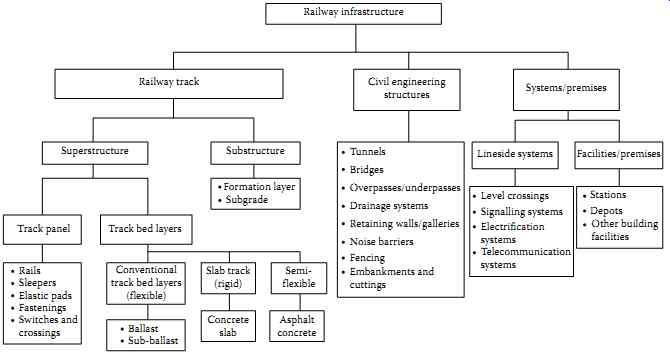
FIG. 1 Constituents and components of the railway infrastructure.
===
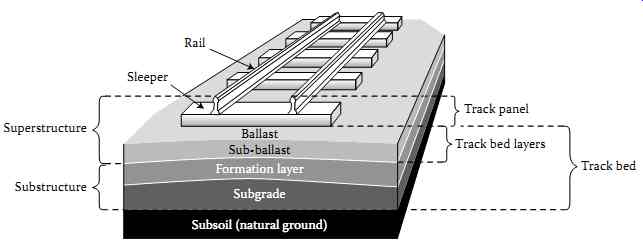
FIG. 2 Railway track.
Components: Rail Sleeper Ballast Sub-ballast Formation layer Subgrade Subsoil (natural ground) Track panel Track bed layers Track bed Superstructure Substructure
===
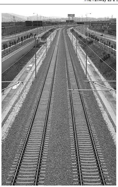
FIG. 3 Railway track; ballasted track superstructure, Rail fastening
Rail pad DEX anchor bolt Adjustable baseplate Adjustment plate Rail
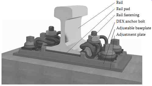
FIG. 4 DFS (Direct Fastening System) with adjustable steel baseplate.
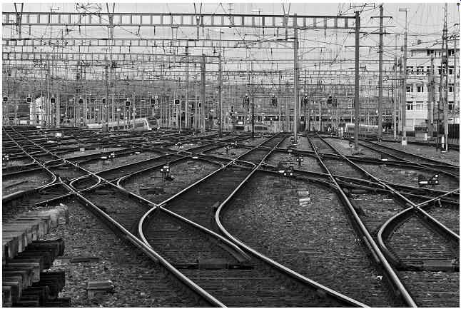
FIG. 5 Switches and crossings configurations, Zurich, Switzerland.
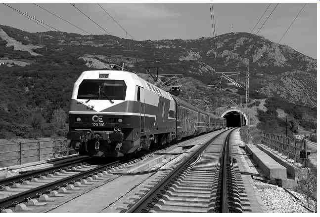
FIG. 6 Slab track - Tunnel at Tempi, Greece.
A third trackbed system seldom applied is the 'asphalt concrete trackbed', or otherwise called 'semi-flexible trackbed'. This solution is used in certain occasions in Italy and Japan for the construction of new high-speed lines. It is also extensively used in North America for the restoration of short lengths in critical segments of the track (tunnels, switches and crossings sections, transition zones before or after major civil engineering works). Finally, this system is an alternative method for the improvement of the mechanical strength of the existing.
The civil engineering structures comprise the tunnels and the underground sections of the track, the bridges, the overpasses/underpasses, the embankments and cuttings, the drainage systems, the soil retaining walls, the galleries, the noise barriers and the fences.
The track systems and premises are separated into:
• Lineside systems that comprise the level crossings and the electrification, signaling and telecommunication systems.
• Facilities and premises that comprise the stations, the depots and other building facilities (administration buildings, warehouses, etc.).
Two special terms are usually used to describe the track structural characteristics along its length
'Plain' track (line): a segment of a railway track that does not have any junctions, crossovers, or points on it.
'Open' track: a segment of a railway track that does not have any tunnels, bridges, over passes, high embankments, deep cuttings and stations/stops on it.
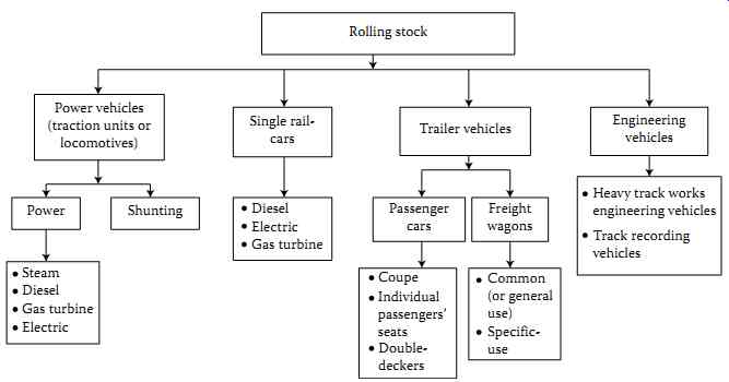
FIG. 7 Categories of rolling stock.
2.2 Rolling stock
Rolling stock is the term employed to describe all railway vehicles, both powered and hauled, used either as power, trailer or engineering vehicles ( FIG. 7).
The power vehicles are self-propelled, that is, they are equipped with traction motors.
These vehicles may...
• Serve the sole purpose of hauling the trailer vehicles, and are then called 'locomotives' (or traction units).
• Transport a number of passengers, and are then called either 'single railcars' (they have a driver's cab at one or both ends) or motor cars.
• To be used for shunting, hence they are called 'shunting locomotives'.
Depending on their traction power used, locomotives are classified into four categories: steam locomotives, diesel locomotives, gas turbine and electric locomotives. Railcars are separated into electric, diesel and gas turbine railcars.
The trailer vehicles are not self-propelled. They serve the purpose of transporting people or goods. They may be classified into three basic categories depending on their function:
• Passenger vehicles (or cars or coaches) intended to transport passengers.
• Freight vehicles (or wagons) intended to transport goods (common or general use freight wagons).
• Specific-use freight wagons intended for the transportation of certain types of freight only.
Also included among rolling stock are the engineering vehicles used to carry out track panel installation works and various track inspection and maintenance works. They are divided into two main categories:
• Heavy track works, engineering vehicles
• Track recording vehicles
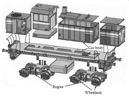
FIG. 8 Main parts of a railway vehicle (locomotive): car body-bogies-wheelsets.
(From Siemens, 2015.)
Every railway vehicle, either trailer or power, consists of three basic parts ( FIG. 8):
• The car body (body shell)
• The bogies (trucks)
• The wheelsets (axle + 2 wheels)
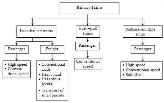
FIG. 9 Types of railway trains.
The combination of locomotives and trailer vehicles forms the loco-hauled passenger or freight trains depending on the category of the trailer vehicles ( FIG. 9).
When two traction units are included in the same train formation then the operation is called '2-loco operation'.
The combination of single railcars, motor cars and/or trailer vehicles forms the railcars.
The railcars can move in both directions without the need of a shunting locomotive in contrast with loco-hauled trains which need a shunting locomotive.
Multiple units (MU) are diesel (DMU) or electric (EMU) trains fulfilling the following characteristics (Connor, 2014):
• Units are made of single railcars, motor cars and/or trailer vehicles semi-permanently coupled
• Driving cab is provided at each end of the unit. Drivers just change ends at the terminus
• Train length can be varied by adding or subtracting units
• Power equipment is distributed along the whole train (only motor cars and single rail cars have power equipment)
Example formations of multiple units are
PR + TC + PR + PR + TC + PR, PR + MC + MC + PR, PR + PR + PR + PR where
PR: Single railcar
TC: Trailer vehicle (car)
MC: Motor car
Push-pull trains are hauled passenger trains with ( FIG. 10):
• A locomotive at the front (pull-push) or at the rear (push-pull)
• A trailer vehicle at the rear or at the front, with a driving cab allowing the train to be driven from either end (Driving Van Trailer)
• A number of intermediate passenger trailer vehicles Push-pull trains can move in both directions without the need of a shunting locomotive unit. The locomotive is controlled remotely through a train cable length when the Driving Van Trailer is leading.
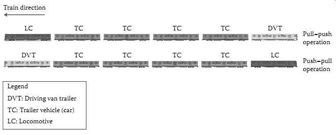
FIG. 10 Push-pull train operation.
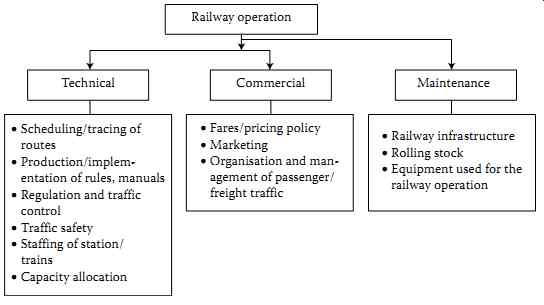
FIG. 11 Technical and commercial railway operation activities.
2.3 Railway operation
The term railway operation describes all activities through which a railway company secures revenue service.
Railway operation may be broken down into technical and commercial. FIG. 11 presents the activities of both technical and commercial operation.
Sound maintenance is a prerequisite for the smooth operation of the railway system.
Maintenance is characterized as a 'horizontal activity', since it applies to all three constituents of the railway system.
3.1 Description of the system
The two basic 'technical units' securing the 'transport' with railway means are the vehicle's wheelset and the rails ( FIGs. 12 and 13).
The wheelset consists of three basic parts:
• The axle
• The wheels
• The axle boxes
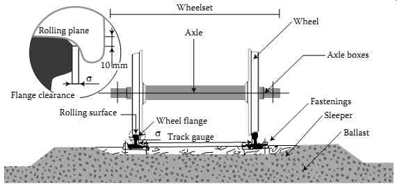
FIG. 12 Rolling of a conventional railway wheelset on rails.
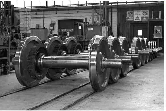
FIG. 13 Railway wheelsets
The wheels consist of
• The wheel tread, being the outer section of the wheels that allows the rolling on the rails
• The wheel body Over the last 30 years, all freight and passenger vehicles running at speeds V > 160 km/h have been equipped with cast wheels (wheel rim and body being a monobloc).
The wheel flanges (one on each wheel) are characteristic of the inner section of the wheels; their mission is to prevent derailment in case the wheelset lateral displacement exceeds the limits set by the track gauge ( FIGs. 12 and 1.14). Meanwhile, the flanges support the wheelsets' self-guidance when passing through switches and crossings configurations ( FIG. 15).
The wheel cross section (profile) is not orthogonal as it is in the case of road vehicle tires.
It features a slight variable conicity that 'is open' toward the inner part of the track (FIGs. 16 and 17).
The two wheels are rigidly connected through a cylindrical rod (axle) resulting in the rotation of both the wheels and the axle at the same angular velocity ?.
The above 'wheel-axle' system is called conventional (or classic); the wheelset runs a steel guideway consisting of two parallel rails set at a fixed distance between them (rail inside face) commonly called the track gauge ( FIG. 12).
The rail consists of three main parts ( FIG. 18):
• The head
• The web
• The foot
The upper surface of the rail head is curved, and hence, forms the surface over which the wheel treads run.
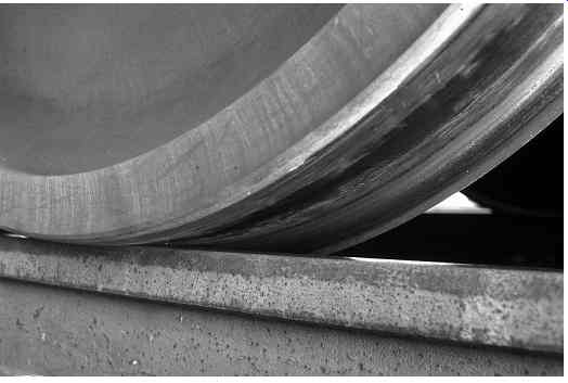
FIG. 14 Railway wheel rolling on plain track.
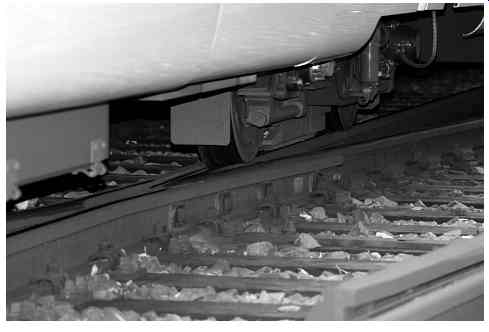
FIG. 15 Railway wheel rolling on crossing's frog area.
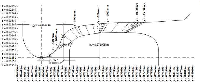
FIG. 16 Wheel-rail contact surface geometry.
Rails are mounted on sleepers at a certain angle, called rail inclination angle (usually 1:20 or 1:40) ( FIG. 19). This layout improves the transversal stability of the vehicles in a straight path.
3.2 Fundamental functional principles
During wheel rolling, elastic forces develop on the contact surface (creep, gravitational forces). Under smooth running conditions (good track ride quality, allowable speed limits, rolling stock in good condition), these forces guarantee the stability and guidance of vehicles on straight paths and in curves.
The generation of these forces comes about through ...
• The specific profile of the wheels
• The rigid connection of the wheels to the axle
• The geometry of the upper outer part of the rail head surface
• Creep phenomena
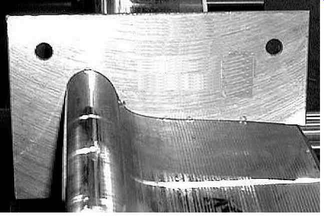
FIG. 17 Geometry of rolling surface of the wheel.
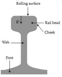
FIG. 18 Main rail parts.
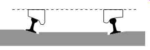
FIG. 19 Inclined rails on sleepers.
3.2.1 Running on a straight path
We consider a conventional railway wheelset centered on the track, running at a constant speed, V, on a straight path. If for any reason (track geometry defects, wheel asymmetry etc.), the axle is displaced transversally with regard to the initial equilibrium position, then, due to their profile, the two wheels roll with different radii (r1 ? r2).
In the case of FIG. 20 r2 > ro > r1 applies (where ro the rolling radius of the two wheels in the initial equilibrium position). Owing to the rigid connection of the wheels to the axle, both wheels have the same angular velocity, ?, and consequently the Equation 1.1 applies
?r2 > ?ro > ?r1 ? V2 > V > V1 (1.1)
(V1, V2: relative velocities of the two wheels).
The wheel running at a relatively higher speed (wheel 2) will overtake the other wheel (wheel 1), and due to the rigid wheel connection, this will cause a rotation of the axle with regard to the transversal axis _ y. 0
Owing to the simultaneous forward rolling of the wheelset, the rolling radius r1 of wheel 1 constantly increases while the rolling radius r2 of wheel 2 constantly decreases. When r1 > r2 wheel 1 starts overtaking wheel 2 the phenomenon is repeated.
This motion of the wheelset is known as 'hunting' oscillation.
In reality, the motion of a railway wheelset and, especially, of a complete vehicle (car body + bogies) is more complex. Owing to the simultaneous motion of the wheelset at a constant speed V, when the rolling direction of the wheels does not coincide with the vehicle displacement direction, friction forces are created on the wheel-rail contact surface (creep forces), and alter the kinematic behavior described above, thereby giving the wheelset a dynamic behavior.
At very low speeds, this physical mechanism guarantees the stability of the vehicle. Yet, at high speeds, high-amplitude oscillations are created and the motion becomes unstable. In such case, vehicle stability is secured, thanks to the longitudinal elastic connection between the bogies and the wheelsets (primary suspension), which limits the amplitude of oscillations. Should the wheel transversal displacements exceed the anticipated flangeway clearance, the rolling of the wheels on the rails is secured by the presence of wheel flanges (FIG. 12).
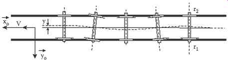
FIG. 20 Sinusoidal motion of a railway wheelset (hunting).

FIG. 21 Movement of single railway wheelset in a curvature of track.
3.2.2 Running in curves
Let us examine the layout of FIG. 21. Upon entering the curve, the wheelset is displaced by 'y' with regard to its outer face. Owing to the conic profile of the wheels, the initial rolling radius ro of the two wheels changes into r1 and r2 for the outer wheel and the inner wheel, respectively.
The rolling radius of the outer wheel is bigger. The inequity r1 > r2 applies, and by extension, V1 > V2 also applies (where V1, V2: relative velocities of the two wheels).
Owing to the rigid connection of the wheels, the wheelset tends to rotate by itself toward the inner face of the curvature, displaced by yo, seeking for a radial positioning inside the curve (the two wheels cover unequal paths).
As in the case of running on straight sections of track, when the wheelset transversal offset exceeds the existing flangeway clearance 's', the running of the wheels on the rails is secured by the presence of flanges.
The motion described above concerns a single isolated wheelset. The bogie negotiation in curves is more complex and the axle's positioning is affected by the motions of both the bogies and the car body. However, the wheelset inscription mechanism in curves remains the same.
Since the birth of the railway (1825) till now, the system described above represents the basic unit materializing the physical mechanism of guidance of the railway vehicles on a straight path and in curves. Unlike other means of transport, railway vehicles do not require human intervention (steering wheel operation) or complicated mechanisms.
At this point the following classification of curves is proposed, based on the range of the horizontal radii values Rc.
• Rc = 5,000 m Very big radii
• 2,000 m = Rc < 5,000 m Big radii
• 500 m = Rc < 2,000 m Medium radii
• 250 m = Rc < 500 m Small radii
• 100 m = Rc < 250 m Very small radii
• 20 m = Rc < 100 m Tramway network radii
3.3 Distinctive features of railway systems compared to road means of transport
As a system of mass terrestrial transportation, the railway differs from the road means vis-à-vis its three constituents, that is, the railway infrastructure, the rolling stock and railway operation.
• The railway has only one degree of freedom. The one degree of freedom facilitates the automation of a range of operations such as driving, signaling, braking, electrification. Conversely, unlike the road vehicle, the railway cannot provide 'door to door' services (rigid system).
• Owing to the low adherence between wheel and rail (steel/steel contact) and the greater braking weight, the braking distance of a train is, for the same speed, much greater than that of a road vehicle; since braking seldom prevents a collision, it is of great importance that the railway can 'prevent' such accidents by taking those measures necessary in order to avoid collision condition.
• On the road arteries, the traffic lights are virtually always time regulated (time period for traffic signals). The opposite applies to the railway where regulating of the trains is based on the location of the railway vehicles.
• Railway vehicles, by contrast with road vehicles, do not need to be guided by human intervention (steering). The direction of movement is determined by the steel guideway only.
• Trains possess operational and constructional features which increase the aerodynamic phenomena as they move (high speed, great length, large frontal cross section). These phenomena may have negative consequences on the rolling stock, the passengers, the users of the system who are on the platform and the staff working near the track.