12. Rail wear
Abrasive wear occurs when there is contact between the side of the flange of a wheel and the gauge face of the rail. This contact usually takes place between the leading outer wheel of a vehicle bogey and the outer rail of a curve.
On curves, careful periodic check must be carried out of the outer rail to ensure that side wear is kept within prescribed limits. Failure to do this could result in a derailment.
Where curves are tighter than 200 m radius, continuous check rails should be provided inside the inner rail. This check rail is to be set not more than about 50 mm inside the running rail or at a distance that will ensure that the inside face of the flange of the inner wheels will bear on the check rail thus sharing the centrifugal force between the check rail and the outer rail through flange bearing.
Abrasive wear of rails can be reduced by the use of rail lubricators placed at strategic positions. Great care needs to be exercised in the use of lubricators to ensure that only flanges are lubricated. Lubricant deposited on the top of rail heads can cause problems with braking, acceleration and wheel-spin.
This is particularly important where trains are automatically driven or where stopping positions are critical such as when rolling stock doors have to line up with platform doors.
When wheels run along fairly straight track with flanges just clear of the rails, the contact area between wheel and rail is extremely small. In theory the contact would only be a point which would make contact pressures infinitely high. In practice both surfaces deform slightly to give a contact 'patch'. Even so typically such a patch has only an area of about 100 mm2, under the heaviest wheel load. This gives pressures as high as 1200 N/mm2 which is higher than the yield point of the steel. This has the effect of causing the contact patch to become plastic and to flow causing various wear patterns and irregularities over time.
Where rails become side worn near to limit on curves, extra life can be obtained by either turning the high rail on jointed track or transposing the two rails on continuously welded rail. Close inspection of the existing inner rail outer edge must be carried out before transposing to ensure that there are no other defects present such as roll-over, 'lipping' or plastic flow that would make the ride rough and precipitate failure of the new running edge.
If speeds in excess of 120 km/h (75 miles/h) are expected transposing should only be carried out if re-profiling of the existing inner rail is carried out.
Wear on point and crossings needs to be carefully watched on a regular basis. Some repair of bad wear can be done by welding but in most cases components need to be changed.
In jointed track, excessive wear often takes place at rail joints or fishbolt holes and is the main reason for re-railing. Joints also increase wear on rolling stock. This is one of the main reasons why main line railroads are progressively changing to continuously welded rails.
When a derailment occurs on any railroad at any location, rail wear must be fully investigated as this can often prove to be the root cause. All rails should be closely inspected including any tell-tale signs of where wheels ran at the time of the derailment.
13. The desirability of removing rail joints
The earliest memories of many from childhood days relate to the 'Clackerty- clack' of steam railroads.
In those days every schoolboy knew that rails were sixty foot long and had to have fairly loose bolted joints so that the rails could expand in the hot weather and contract in the cold. Well understood also to the regular suburban commuter was the familiar sight from the carriage window of the platelayer driving in keys and greasing fishbolts.
To many career railroad men however these 'chores' represented a sizeable annual workload and removal of joints, if it could be done practically and safely, would be a giant leap forward. Apart from the reduction of potential track irregularities and smoothing and quieting down of the ride, removal of rail joints would clearly show a reduction of wear on wheels and rolling stock components in general. There would also be an improvement in the performance of underframe and bogie components subject to fatigue.
Up to the outbreak of the Second World War in 1939, mechanical, civil, structural and marine engineers had all used bolting and riveting as the main method of joining together steelwork in its various forms.
During the War, metal arc welding began to be used for the first time and after the War welding began to be used extensively, particularly in structures, machines and ships.
14. Introduction of track welding
In the immediate post-war years, certain wartime teething troubles with metal arc welding were eventually ironed out and better understood, as wider experience was gained. In particular, failure of welds or the parent metal in the heat affected zone of welds by metal fatigue took some time to understand and correctly predict. These fatigue failures were particularly troublesome in some of the early welded ships and to a lesser extent in some welded bridge members.
Metal arc welding was used extensively on steel structures in shop fabrication. By the late fifties, shop welding of this type had completely replaced the earlier shop riveting of structures, site joints generally being site bolted or very infrequently, site welded.
Although some metal arc welding and electroslag welding is used for the fabrication and repair of point and crossing work, the welding of rails end to end to form continuous welded rail (CWR) is carried out in the shops by a process known as Flash Butt Welding (FBW). Flash butt welding of rails commenced in the UK on a large scale in the late 1950's and since that time, the process has been refined and improved but still remains basically the same. In the mid 1950's, London Transport introduced flash butt long welded rails using the standard bullhead section.
The FBW rails were produced by welding five standard sixty foot lengths into a long rail of 300 ft (about 90 m). These rails were joined using 'tight' bolted joints where the fishplates were clamped to the rail using high strength friction grip bolts, tightened to a predetermined torque. London Transport (LUL) are now in the process of changing over to flat-bottom rail.
Main line railroads in the UK use flat bottom section rail for CWR which is flash butt welded in the shops in lengths up to 240 m. In recent years in the UK British Steel PLC have been able to supply long lengths of rail already flash butt welded into long lengths.
15. Shop welding to produce long rails
The process of Flash Butt Welding is used in the shops to join rails which are later to be incorporated into Continuous Welded Rail sites. This process involves clamping the rails at a predetermined gap distance and passing a high current across the gap at a low voltage, during which the work pieces are brought together.
Electrical resistance heating first causes contacting surface irregularities to melt and subsequently raises the temperature of the whole interface to near melting point. Once the components are sufficiently heated they are forged together, and excess molten steel at the interface is forced out of the weld area.
The stages of FBW in the shops include burn off, preheating, flashing, forging and post weld treatment.
Once the weld has solidified, integral shears at the welding plant remove the excess upset from the periphery of the weld, leaving about 1 mm proud all round the weld section.
The welds are then straightened and the railhead ground to give a smooth profile for the weld along the length on the rail.
Unlike metal arc welding, no electrodes or added metal is used, only the parent metal is fused. Because some of the metal at the rail ends is forced out of the section profile, the overall effective length of the rail reduces by about 20 mm for each weld.
16. Site welding to produce CWR
On arrival at site, long rails are welded to form CWR using the Thermit or alumino thermic welding process. This method, which was discovered in 1896 by Hans Goldmidt, is based on the reduction of heavy metal oxides by aluminum. Thermit welding was first used in Hungary in 1904 and most of Europe had adopted the process for site rail joints by the late 1920's. The process was not used very widely in the UK however until the 1950's.
Some light railroads have used Thermit welding of short rails throughout without the use of FBW into long rails beforehand. Although this is cheaper and removes the need for a shop process, the practice is not recommended for railroads carrying heavy axle loads.
Thermit welds are completely satisfactory but have less consistency than FBW, being carried out in the open on site rather than in controlled workshop conditions.
Annual statistics, published on reported broken rails at welds in the UK over recent years, strongly bear out the better performance of FBW in practice.
In this process, the rails to be joined are set in position, fixed in their baseplates, with the ends properly aligned and with a gap of 22-26mm between them. A refractory mould is then placed around the joint and a thermit portion is ignited in a refractory crucible above the mould. The portion is a combination of powders which after reaction will produce a weld metal which matches the chemistry and metallurgy of the parent rails.
When the reaction is complete, the crucible is tapped and steel pours into the moulds to form the weld. Slag, being less dense than the steel, remains at the top of the mould. The weld is allowed to cool after which the excess metal, mould material and slag is trimmed away and the joint is ground to profile.
FIG. 7 Continuous Welded Track.
17. Stressing or 'Locking-up' of CWR
With jointed short rails, the object is to allow rails to expand and contract during extremes of temperature to avoid the build up of compressive and tensile stresses.
In long welded rails and CWR however, the rail is constrained so that it cannot expand or contract. In this case, in order that the rail shall remain at its original length, the rail undergoes compressive and tensile strain, which is equal and opposite to thermal strain.
By simple calculation using Hooke's Law, (F = strain x A x E), it can be seen that a restrained standard BS113A FB rail increased in temperature by say 45°C will produce a force of 76.5 tonnes in the rail.
A compressive force of such magnitude in hot weather is sufficient to cause a buckle of the track and it is essential for safety that development of such a force is prevented. Similarly, high tensile forces in extremely cold weather can cause brittle fracture of rails and must be avoided.
This is done on CWR by artificially extending the rail at the time of installation and fixing it down in a state of tension. The ideal is to fix the rail at a length that it will be, at a temperature that is exactly halfway between the hottest and coldest likely rail temperature. In the UK this is generally accepted as a temperature of 27°C. The rail may be artificially extended by rail warming or, as is now more usual, by stretching with a tensor.
18. Points, switches and crossings
All railroads require points or 'turnouts' to be able to divert trains from one track to another and crossings or 'diamonds' to allow trains to cross other tracks at an angle.
This applies to all railroads from the most complicated reversible layouts at terminal stations to simple single track tramways with passing loops.
Any assembly of points and crossings is called a layout. Some layouts occur frequently and have acquired their own names. The most common is the 'crossover' which is simply two sets of points laid crossing to crossing in adjoining track enabling trains to change track in one direction. If two crossovers are superimposed, thus enabling movements from either track in either direction, the layout is known as a 'scissors crossover' for obvious reasons. In this layout there are four sets of points and one diamond.
Points or turnouts and diamonds are themselves composed of elements known as crossings and switches.
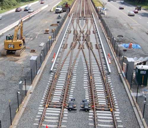
FIG. 8 A crossover layout.
19. Crossing design and manufacture
A crossing enables a wheel travelling along a given rail to pass through the rail of a track which crosses its path. Where two tracks cross each other at an angle, there are four crossings which make up the resulting diamond.
Unless the tracks cross at right angles, there will be two Obtuse Crossings and two at an acute angle known as Common Crossings.
'Built-up' crossings are manufactured from standard rail and are perhaps the most often seen, having been used traditionally on railroads for many decades. In these crossings the four components, the point rail, the splice rail and two wing rails are cut, bent to shape, drilled and machined as necessary and then bolted together as a complete assembly. This type of simple crossing has given good service over many years in countries all round the world. They are subject to wear however, particularly at the tip of the point rail and where the point and splice rail bear against one another.
Through bolts also often work loose under traffic.
A 'part-welded' crossing consists essentially of the same four rails as a built-up crossing and is usually made of standard rail. The assembly however is strong enough to take thermal loads and consequently it can be welded into CWR, leaving only the flange way gap as a source of wheel/rail impact.
In theory at least, this is a considerable advantage over both built-up crossings and cast crossings, although welding in of components into point and crossing layouts can have a significant time disadvantage when work becomes necessary during possession.
The 'Vee' of a part welded crossing is prepared by machining two pieces of rail into a symmetrical straight splice with a weld preparation milled into the head and foot. The electroslag welding process is used under carefully controlled conditions to produce a continuous homogeneous weld. This welding is laid down automatically with top and bottom welds being done simultaneously to keep any distortion to an absolute minimum. The complete crossing assembly is held together using high strength friction grip bolts tightened to a specified torque or by 'huck' bolts.
Another form of crossing is the cast Austenitic Manganese Steel (or AMS) crossing. In this case there is only one 'monobloc' component making up the entire casting. The casting is made by pouring this special molten steel into a mould which represents the shape of all four components used in the other types of crossing.
This type of crossing is favored by many railroads due to its very high wear resistance and long life. Also due to being monolithic, there is no relative movement of components and the ride is generally very good.
Another advantage is the ability to combine more than one crossing in a single casting, as is sometimes the case on a tight scissors crossover.
In spite of its advantages however, AMS crossings do have some disadvantages. Casting as a process is always subject to internal cracking due to cooling and these faults are sometimes difficult to detect before installation.
Also when faults do arise in service, the castings are much heavier and more unwieldy to handle during a limited possession than built-up crossings, particularly in tunnel.
Check rails are provided opposite crossings. Their function is to control the alignment of the wheelset so that it is not possible for the wheel moving across the gap in the throat of the crossing to strike the nose of the crossing or to take a wrong path.
20. Points or turnouts
Points or turnouts, as shown below, enable vehicles to be diverted from one track to another and consist of a pair of switches and a crossing, connected by closure rails.
======

FIG. 9 Components of points or turnouts.
Sole plate.
1st stretcher bar.
2nd 8 subsequent stretcher bars.
Minimum switch opening 50mm.
Toe opening 108mm (105mm min., 108mm ma., for Clamp Lock operation). To 'hand' switch stand at 'A' and look as shown.
Left hand stock rail.
Left hand switch rail. 1 Left hand 'h set
Right hand switch rail.
Right hand stock rail. 1 Right hand 'h set
Slide baseplates.
Heel baseplates.
Stress transfer blocks.
======
In a set of points the fixed rails on either side are known as stock rails, the moveable rail being known as the switch rail. The switch rail is machined to a sharp tip or toe at one end and the tapered portion of the switch rail is known as the switch tongue. The switch tongue is machined to fit snugly into the stock rail in the workshops. It is unwise, when worn to change a stock or switch on its own and both should be changed as a fitting pair. Two movable switches should be held in the correct relative position to each other by at least two stretcher bars.
If the set of points is so arranged that in the predominating traffic direction the tracks diverge, it is known as facing points. If the main traffic direction is such that the two lines merge, they are trailing points.
21. Driving, locking and detection of points
In the early days of railroads, sets of facing points on passenger lines were avoided because of the high risk of derailment due to wheel flanges 'splitting' stocks and switches. Following this early experience, it became mandatory that all facing points should be locked in position and that the position of each switch should be 'detected' in relation to its mating stock rail.
On modern railroads, points are operated by electric or compressed air point motors/machines which operate the points, lock and clamp them in position and also detect whether or not the switches are fully 'home'. There needs to be careful and clear division of responsibility for maintenance and adjustment of all point mechanisms between signal and track engineers.
22. Conductor rails and components
Where railroads are electrified using either third rail or fourth rail DC systems there are a number of other components and fittings which are track related.
Conductor rails are usually made from steel which is designed to be of high electrical conductivity, containing much less carbon than for normal rails. This means that steel conductor rails are softer and of lower strength than running rails. The rails can be jointed by bolted fishplates or welded.
In recent years, some light rail systems e.g. DLR, have used aluminum conductor rails for underside contact, with a wearing surface of stainless steel.
Conductor rails are supported by insulators fixed to sleepers at frequencies depending on track curvature, location and type of fixing. The insulator assembly usually consists of a porcelain pot with a cast malleable iron cap having two upstanding 'ears'. These ears locate the conductor rail transversely without restraining longitudinal movement. The insulators are fixed to the sleeper using a pair of wrap round base clips.
At discontinuities and ends of conductor rails, ramps are provided, also supported on sleepers, to pick up and lower collector shoes on rolling stock.
It is important that these ramps, which can be welded steel or cast iron are regularly checked to ensure that line and level is correct. Failure to do this can result in damage to rolling stock or track or both.
23. Paved concrete track
Paved Concrete Track (sometimes known as PACT) is a continuously reinforced concrete pavement laid by a specially designed 'slip-form' paver.
This machine runs on accurately positioned guide rails which ensures that the concrete pavement line and level is very closely controlled. The guide rails are often the long welded rails which will subsequently be repositioned and used as permanent running rails.
The rails are usually supported on baseplates which may have some form of resilience incorporated into their design. Even though the concrete has been accurately positioned, the tolerances achieved may be more than is desirable for accurate positioning of the rails. It is desirable therefore that some adjustment capability is built into the system of final positioning of the baseplates or cast-in fixings. One way of achieving this is for the rails to be finally positioned to line and level on temporary packs/wedges with baseplates and fixing bolts hanging off the rail. Once final rail position is fixed, any gaps at fixing holes and under baseplates can then be grouted up or filled using epoxy mortar.
This track system is much more expensive than conventional ballasted track and cannot be easily modified once laid. It is however of particular use in existing main line size tunnels, where the shallow construction depth may permit the achievement of increased overhead clearances for 25 kV electrification or for the passage of large container trains. In this track system particular attention needs to be given to drainage channels.
24. Cast-in precast sleeper track
As a cheaper alternative to PACT, prestressed or reinforced concrete sleepers or special purpose made units can be laid in position accurately with rails fully adjusted and then a concrete slab poured between and around them.
In this case, holes through the sleepers are left for transverse reinforcement or some 'hedgehog' starter bars are provided to assist both the precast and in-situ elements to act as a whole.
25. Floating slab track
In locations where it is vitally important to reduce noise and vibration to an absolute minimum, floating slab track may be considered. It should be stressed that this type of solution is very expensive, requires a lot of space and can only be justified where railroads run very close to or under concert halls, churches or operating theatres etc.
In this form of construction the trackform, which may be ballasted or non-ballasted, is supported on a structure which is isolated from the supporting ground by soft resilient bearings.
A notable example of this type of construction is to be found in London under the new Barbican Concert Hall.
26. Track installation and renewal
Up to the late 1930's most railroads installed or renewed track mainly 'piece-small', using a large amount of skilled labor, only assisted for heavy lifts by rail mounted steam cranes.
In more recent years, special 'purpose-built' equipment has been produced, in particular for surface main lines which mechanizes much of the track laying process. Large machines can now lay panels of sleepered track or place individual sleepers, to be followed by plant laying welded rails in very long lengths.
Because of space restrictions in tube and other small bore tunnels, much of the laying of tracks in these tunnels is still carried out piece-small, using manual methods but using power tools and aids wherever possible. This has the added complication in tube tunnels that night possessions for renewal work are short and track has to be made safe each morning for a further day's running.
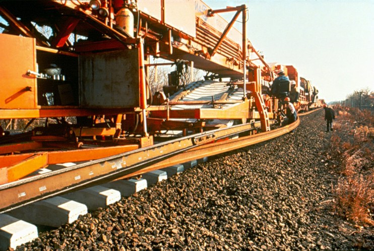
FIG. 10 Main line track installation -- used by Amtrak USA in 1978.
27. Day-to-day maintenance of track
The passage of trains coupled with the effects of varied weather and day/ night conditions, causes steady deterioration of even the best constructed railroad track unless proper day-to-day maintenance is carried out.
Activities of others alongside the railroad and trespassers and vandals on the railroad can also effect track conditions of safety.
Both visual inspection of condition and mechanical measurement of track geometry is necessary to establish a quality standard and to determine whether the standard is being maintained or not.
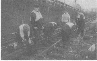
FIG. 11 Day time maintenance gang at work.
All railroads require a track maintenance organization to ensure adequate inspection is carried out and that proper resources are available to attend to minor matters on the track and immediate surroundings as they arise.
On surface lines, where it is possible to safely stand to one side to allow trains to pass, much daily inspection and local adjustment can be carried out during traffic hours.
On underground railroads or other urban railroads where clearances are tight and trains are frequent, access for staff is not usually available during traffic hours. In this case maintenance staff must be organized to be on duty at night during non-traffic hours. For these railroads all inspection and adjustment of track must be done at night and cannot be watched or further adjusted during the following day except under special protection arrangements which will inevitably delay trains.
Regular major maintenance activities which will obstruct traffic or endanger staff, need to be arranged during non-traffic hours or in a 'possession' of the track specifically arranged for the purpose. Such major activities might well include ballast tamping, drain rodding, rubbish clearing, block joint changing, fence repairs close to the track and replacing individual damaged sleepers, chair castings or rails.
Prev. | Next
Top of Page | Article
Index