1. The early history of railroad signaling
From the very beginning of railroads, it was soon realised that some form of signaling to control the movement and speed of trains is necessary if there is to be any degree of safety from collision. Even before the introduction of steam locomotives, when horses were the most common means of providing haulage power, accidents were prone to happen on tramways because of the difficulty of providing enough brake power to overcome the inertia of a train of heavily loaded vehicles. Once locomotives were introduced with more power, higher speeds and longer trains behind, stopping became even more difficult and hazardous.
Because of this, it quickly became obvious that some means of signaling was necessary to indicate to a locomotive driver, well in advance, whether he needed to slow down and stop his train under controlled braking or could proceed at speed.
In the early days, each railroad company employed men called policemen who were posted at stations, junctions and other important places such as level crossings, to control the running of trains. Initially they signaled to the drivers using hand signals. These early policemen were organized very similarly to the Metropolitan Police and their duties included keeping general law and order on railroad premises and removal of trespassers as well as operating points and signaling trains.
There was no means of communication between individual policemen controlling trains who allowed trains to pass on the rash assumption that if enough time had elapsed since the previous train then the line was likely to be clear! With this primitive type of control, accidents were not as frequent as one might expect but when they did occur they were sometimes very serious and caused casualties.
By the middle of the nineteenth century, many railroad companies had developed some form of filed signal to replace hand signals and some grouping of signal and point levers in a common 'frame' was seen. This was the forerunner of the signal box. In 1860 the first installation in which levers were interlocked so that signals could not be 'cleared' until points were properly set, was brought into service.
This principle of interlocking has remained with railroads ever since and is fundamental to the safety of any signaling and train control system.
Another such principle became known as 'fail-safe' and this too had to be learned in the hard school of experience. Originally fixed signals had to be turned or moved in some way to indicate a clear road. Because of a number of accidents with this type of arrangement, it soon became apparent that signals could stick in the clear position or wires could break without the possibility of turning the signal to the danger position. Following this all semaphore signals were designed to have counterbalance weights which returned the signal to a 'danger' position in the event of failure of any components.
These two principles of interlocking and fail-safe remain today and are fundamental to the safe operation of all signal equipment and systems.
The other great need in early railroads was to have some form of communication between signal boxes. Again by about 1860 a simple method of indicating that a train was 'on line' or 'clear was invented giving this vital link for the first time. The system was made possible by an arrangement of electro-magnets with a low current passing through to indicate by a needle whether or not a train was still on the line between the boxes or had passed to the next section of a track. This was a tremendous step forward and removed for good the danger of a broken down train blocking the path of the next train which was signaled through on the assumption that sufficient time had elapsed for the road to be clear.
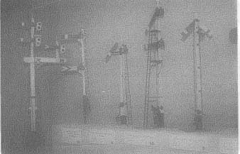

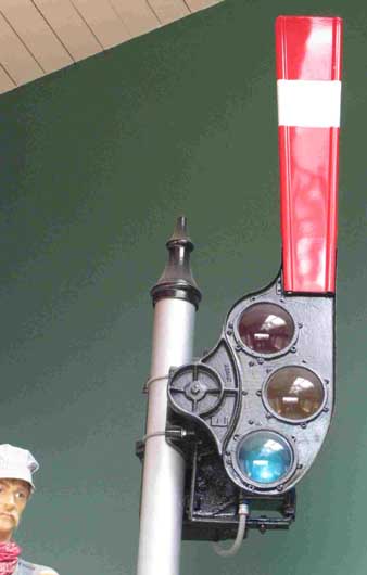
FIG. 1. Semaphore signals.
2. Modern signaling principles
All modern signaling systems have the following six basic objectives:
- control trains in a safe manner for the conditions ahead.
- maintain a safe distance to any train ahead or dead end ahead.
- prevent the setting of conflicting movements.
- ensure that points are locked in the correct position.
- enable trains to operate to the headway required.
To enable trains to operate to the scheduled speed with minimum disruption consistent with safety.
By far the most dangerous movement of trains is when passing over points and crossings. It is vital that trains are kept from moving into any position of danger and are only allowed to proceed when all train movements are properly co-ordinated and when the route ahead is properly set and clear.
The spacing of signals depends to a large extent on the minimum time interval that is required between trains, known as the headway. On a main line railroad where mixed stock passes at different speeds, spacing of signals becomes a complex subject. On rapid transit railroads and light railroad systems it becomes more straightforward as the trains tend to have the same movement characteristics.
Once signal boxes had a positive means of knowing whether or not sections of track were definitely clear of trains, it was possible to introduce what became known as the 'block system'. The specified lengths of line between boxes, stations or junctions, termed block sections, formed a space interval between trains. The block system principle, which states that not more than one train should be allowed on one line in a block section, was established, a principle that continues to be the basis of modern signaling today.
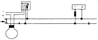
FIG. 2. The DC track circuit.
3. Track circuits
The simplest and most effective way of detecting that there is no train on a particular length of track is by the use of the track circuit which is shown in diagrammatic form in FIG. 2 below.
In this simple arrangement, the current flows from the battery to the relay through the rails and the green light is operated from the relay. When an approaching train reaches the section, the axles short circuit the current from the relay which then drops and the green light goes out and a red light comes on, fed from the relay contact.
This is a 'fail-safe' arrangement as if the battery goes flat, a rail breaks or a contact becomes loose etc, the result is the green light goes out and the red light comes on.
4. Point operation, locking and detection
As has been stated previously, movements over points and crossings are the most dangerous and therefore point equipment requires the most built-in safeguards. The potential hazards to safe operation from points arise from the possibility that they will be set in the wrong direction or that they will come open during the passage of a train.
To prevent points coming open, they are locked in position for a facing move and to ensure that the train is not allowed to proceed over them until they are safe, they are 'detected' to be in the correct position, fully 'home' and locked.
The lock is held until it is proved that there is no train passing over the points by means of the track circuits, and is applied from the moment that a train approaches to within its braking distance of the toe of the points.
This is to prevent a signal man from moving the points after a train has accepted a signal.
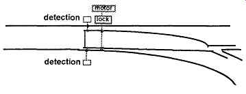
FIG. 3. Diagram showing point locking and detection.
Points on early railroads were operated by hand worked levers, usually close to the points themselves. Later, they were still hand operated but the levers were more remote from the points and grouped into frames, along with signal levers. Considerable skill and strength was required to 'throw' point levers that were some distance from the points because of the friction and inertia to be overcome.
Although some points in depots and sidings continue to be hand worked, most modern railroads now use some form of motor to move points from one position to another. These motors are usually electrically driven but can be driven by compressed air, as on the London Underground.
With modern point motor assemblies, devices are integrated into the mechanism which will lock the points in position once they are fully home and will also electrically detect that they are actually fully closed. They have the added advantage of being able to detect the presence of an obstruction, such as a discarded can, in the point blades.
5. Interlocking
The interlocking of signals and points is another principle born out of hard experience in the early days, which is now universally adopted. In essence interlocking is introduced to prevent signal men accidentally clearing a signal before points are properly set or clearing signals that would allow a conflicting movement. In manual boxes, a series of sliding bars is connected to the levers. These bars have notches and dogs in them which will only allow operation of the signals in correct relationship to other signals and when relevant points are correctly set.
Similar devices are incorporated into power operated boxes which follow the same principles and prevent operation of signals or points for conflicting moves. Similarly signals cannot be cleared in areas of pointwork until the correct route is set and all trains are clear.
From the foregoing, it can be seen that railroad signaling is basically simple and can be made absolutely fail-safe for all conditions providing the following three basic sub-systems are in place and working:
- Track circuits
- Point locking and detection
- Interlocking
6. Minimum headways
The headway of a particular train service is the minimum time interval that can be run between trains. The most critical point in this consideration is at a station because the station stop or dwell time must be taken into account. The practical minimum dwell time at any station will vary considerably and will depend upon the number of passengers alighting and getting on, the number and spacing of doors on the rolling stock, width of platform, the number of waiting passengers obstructing movement, the proportion of passengers carrying luggage and the percentage of passengers who are familiar daily commuters.
Typical dwell times at busy Metro stations might be expected to be about half a minute reducing on some light rail systems to as little as twenty seconds. Main line semi-fast commuter services at intermediate stops would probably have a station dwell time of at least a minute.
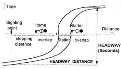
FIG. 4. Headway distance and time.
Headway is measured from the time at which the driver reaches the sighting point of the first signal to a point at which the tail of the train clears the overlap of the signal ahead.
7. Home and distant signals
As trains began to travel faster towards the second half of the nineteenth century, another problem arose with the early semaphore signal systems.
This related to the distance ahead that, an engine driver could be expected to see a signal that was at danger. On a train travelling at say 40mph, a driver would have to react quite quickly to bring his train to a halt at a danger signal even if he could see that signal half a mile away. At double that speed, he still would only have the same viewing distance of a danger signal but to try and stop in such a short distance would at the very least be very uncomfortable, cause damage to the train or the track and might even cause derailment.
To give early warning of signals at danger therefore, all signals were classed as either 'home' or 'distant'. On running main lines, all stop or home signals were provided with a distant signal in advance which indicated whether or not the following home signal was clear. When using semaphore signals, the arms of the distant signals were usually painted yellow with a black vee and notched at the end. Distant signals had green and yellow (or amber) lenses and could be passed only at caution, the driver being then ready to stop at the following signal. Stop or Home signals usually had red painted arms with a white band and square cut ends, their lenses being always red and green only.
Distant signals were placed about three quarters of a mile in advance of the stop signal to which it is applied, the distance depending on gradient and the maximum allowable line speed.
Approaching junctions, twin posted home and distant signals were provided which were thus able to warn the driver which path was clear. Very often distant signals would share the same post as a previous stop signal.
8. Subsidiary signals
Subsidiary signals are used for controlling low speed shunting and other non-running movements both on main lines and in yards. These signals are usually small and at ground level and can allow shunting movements on the main line, calling-on signals for coupling up locomotives to trains and working in the reverse direction to normal. Where signals are difficult to see because of obstructions or tight curves, repeater signals can be provided to overcome that difficulty.

FIG. 5. Two aspect signaling.
9. Two aspect color light signaling
Manually operated systems of signaling and point operation continued well into the twentieth century on most main line railroads in the UK. However, when DC electrification began to be installed, semaphore signaling began to be replaced by electrically powered color lights. On the London Underground, those sections which were electrified, notable the 'tube' lines, were also signaled electrically.
The most simple system of electric signaling is to have signals with two lamps each with a fixed colored lens, red or green for a stop or home signal, and orange or green for a repeater or distant signal.
On rapid transit, metro and light rail systems, two aspect signaling is usually adopted because the braking distances are short due to low speeds and high braking rates, hence the distance needed for the driver to stop the train is usually such as to be able to see the signal in time. Where this is not the case, a repeater signal is placed in front on the running signal to give advanced warning.
For main line railroads, when two aspect signaling is used, a distant signal is positioned in front of the running signal, in very much the same way as was for semaphore signaling.
The initial cost of installing color light signaling is high but the advantages are considerable. Pulling signal and point levers by hand was a skilful but heavy task and severely limited the distances that signal boxes could be apart. Once points and signals were operated electrically, the number of signal boxes could be reduced dramatically and much longer lengths of railroad could be controlled from one point.
FIG. 6. Three aspect signaling
10. Three aspect color light signaling
Where train speeds are higher, or headways are closer, three aspect signaling can be used. This allows trains to approach closer and effectively combines the distant signal of the signal ahead with the running signal. These signals show red, yellow or green indications, corresponding to the night-time red and yellow, green and yellow or double green indications of the semaphore stop signal with a distant beneath it. In color light signaling, the terms distant and home signal no longer apply as every signal has this dual function, depending where the trains are located at any particular time.
11. Four aspect color light signaling
Since the middle of the twentieth century, most new signaling installations on high speed railroads in the UK have been four aspect. With three aspect signaling there is a limitation on the minimum spacing of signals since all signals act as both stop and distant. Signals have to be about three quarters of a mile apart where line speeds are at a maximum to allow an adequate braking distance to be maintained. This has the effect of keeping trains about two miles apart before being checked.
The four aspect system allows trains at higher speeds to slow down earlier and hence to get closer to the train ahead in a controlled manner.
Reading from the top down, the four aspects are yellow, green, yellow and red. The advantage with having red at the bottom is that it can be placed at driver's eye level and there is no lens hood below it which might assist snow to build up and obscure the light. It is a 'fail-safe' principle that maintenance of a red light must take precedence over everything else.
The sequence of four aspect signaling is as follows:
- Green - Continue at full speed.
- Double yellow - Proceed at caution, reduce power, perhaps with some braking depending on type and speed of train.
- Single Yellow - Power off, controlled braking.
- Red - stop.
As can be seen from FIG. 7 below, signals can be spaced closer together with this system and headway times can be shorter, as trains are subject to more control.

FIG. 7. Four aspect signaling.
Unlike semaphore signals, color light signals at junctions do not usually have separate signals for each route ahead. There is normally a single signal with, above it, a route indicator consisting of three or more white lights in a diagonal line at 45" on each side of the vertical, illuminated according to whichever route is set and clear. Sometimes, at complicated junctions or at terminal stations, signals indicate a 'theatre' type or dot matrix illuminated number showing the line or platform number for which the route is set.
At most facing junctions, a speed restriction is placed on the diverging route, and when points are set for the diverging route the signal ahead of the junction will show a single yellow even when the route is clear of trains.
Only when the approaching train has passed this signal and been slowed by it, will the signal at the junction itself clear.
It can be seen from the foregoing that multiple aspect signaling can be extremely effective in controlling trains both on busy plain line and at junctions and termini.
12. Transmission based signaling
The arrival of the micro chip and computers has revolutionized railroad signaling in recent decades. There are now in existence many systems around the world where trains are controlled by computer, including keeping trains on schedule as well as ensuring that there is complete safety and protection to all train movements.
Present and future generations of signaling will use computers extensively to enable trains to be controlled in a closed loop system. Each train is constantly updated from the trackside computer with the maximum safe speed and distance that it can go and in turn tells the trackside its own position and speed. Some metro and light rail systems have introduced automatic running of trains between stations and such AT0 needs to be compatible with the computer controlled signaling and safety systems.
These combining systems are often known as Automatic Train Operation (ATO), Automatic Train Scheduling (ATS), and Automatic Train Protection (ATE'). Absolute compatibility is essential and needs to be checked rigorously.
On such automatic systems, the principles of signaling must still be rigidly applied if safety is to be maintained. Interlocking of points, signals and routes is still a very important requirement to ensure that trains only operate when it is safe to do so.
The main benefits of the use of computers are the reduction in the number of trackside components and the faster recovery from disruption due to the ability to communicate safety information to the train on a continuous basis. Experience has shown that computer control systems need extensive testing after installation before trains can be confidently operated.
A period of several months must be built in to any 'critical path' program to ensure that such testing/commissioning is carried out thoroughly, if early problems are to be kept to an absolute minimum.
In operation, the trackside computer sends messages to the train telling it the value and position of speed restrictions and track gradients ahead and imposes a zero speed restriction at such a point as to protect the train ahead.
The train computer then calculates a target speed and distance from this information, with a safety margin built in to take account of variations such as adhesion characteristics due to weather. The train then monitors itself to ensure that it runs within the maximum speed envelope such that it will stop in time whilst running at the performance level required by the automatic train operation commands. The train also transmits back its speed and position so that other trains can be kept at a suitable distance.
In addition to this, the trackside computer also monitors that the train is operating within the safe speed and sends an emergency brake message if it does not.
To protect against the loss of information, should the train fail to receive a constant stream of valid messages it will apply its emergency brakes.
13. Proof of safety and safety standards
Signaling has now advanced from the position when proof of safety mainly relied on demonstration that components and the system as a whole would always be 'fail safe'. With modern systems, it is necessary to show that the whole railroad system is designed, built, installed, operated and maintained in a safe manner.
This requires that any new design is rigorously carried out and demonstrated to be able to meet the specified level of safety and the application of the system must also be proven to be correct.
The component parts of any signaling and control system must each meet the required the safety level depending on the likely results of failure. For instance, the level of safety required for a component, the failure of which could lead to death, must be of a higher standard than for a component or system, the failure of which could cause people to be misled into a dangerous situation.
Proof of safety and compliance with safety standards needs to be applied to all signal and control equipment, both hardware and software, system design, testing, commissioning, maintenance and replacement.
Formal proof of safety techniques must include detailed consideration of all the possible effects of each possible hardware and software failure. This enables calculation to be made of the mathematical probability of such a failure occurring. In addition, consideration is to be given to the possible action that can be taken when incidents/breakdowns occur. This will highlight possible weaknesses and enable measures to be introduced to prevent matters leading to unacceptable hazards.
Railroad signaling and train control is a complex and rapidly changing subject.
Prev. | Next
Top of Page | Article
Index