IC125: THE CONCEPT
By 1968 it became apparent that Britain needed Inter- City trains to meet a demand for prestige services with limited stops, with a high standard of comfort and able to match the French maximum speed of 200 km/h (125 mph). Gas turbine propulsion was considered, but at that time no sufficiently powerful gas turbine was available for this purpose. It was decided to stay with diesel engines and electric transmission. At the end of 1968 proposals were submitted to the Commercial and Operating Departments of British Rail for a high-speed Inter-City train consisting of seven passenger coaches of a new design (Mk 3), with a diesel-electric power car at each end. Calculations showed that, including all services requirements, a total of 3357kw (4500hp) would be needed to give good acceleration and to cover long stretches at 200 km/h (125 mph).
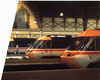
Three lClZ5s lined up in Paddington Station (London),
from where they will leave for Cornwall. Wales and Bristol.
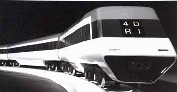
A 1969 model of a possible design for an HST power car
with Mk3 trailers. Note the inclusion of an automatic coupler.
IMPORTANT ADAPTATIONS
The new Mk 3 coaches were designed primarily as locomotive-hauled vehicles and had to be adapted for the high-speed diesel train. The chief difference was the addition of electric cables and connections to carry the control and heating circuits between the power cars. The Mk 3 was an air-conditioned open coach with seats each side of a central gangway, and was made as long as possible within the restrictions imposed by curves and track clearances. The specified speed of 200 km/h (125 mph) would limit the axle load of each power car to 19.35 tons (19 tons), and only a light, quick-running engine could be accommodated. Only one such engine was at that time available from a British manufacturer — Davey Paxman — and the 12-cylinder version of this engine, the Paxman Valenta, would be able to produce the necessary 1678.5kw (2250hp).
Because of the fixed train formation, a change from the usual seating arrangement was tried, and on some experimental vehicles one-way seating was installed. Even so with conventional seating, because the size of the windows was standardized in first and second (standard) class cars, seats no longer coincided exactly with the windows. One-way seating was not popular even though it provided eight more seats in each second-class vehicle. Particular attention was given to smooth riding and low noise levels. With air-conditioning there is no point in letting passengers open windows and, as a result, fixed double-glazed windows were fitted in all but the end vestibules, where door drop-lights had to be used. Automatic doors divide the passenger section from the end vestibules.
Before this time 160 km/h (100 mph) had been the normal maximum speed, and signal spacing was based on the stopping distance of a locomotive-hauled train traveling at that speed. The most important requirement now was to be able to stop a high-speed train (HST) from 200 km/h (125 mph) within the braking distance allowed by the existing signaling. It was this factor that limited the speed of the train to 200 km/h (125 mph).
Standard British Rail air brakes are used. Coupled with disc brakes on all wheels and an additional tread- conditioning brake on the power cars, an HST can stop from 200 km/h (125 mph) in a distance slightly less than an existing locomotive-hauled train from 160 km/h (100 mph). To guard against a wheel or wheels picking up during an emergency or normal stop, a wheel-slide protection device is fitted.
To provide a comfortable ride, a new design of bogie was adopted. It is a lightweight construction with a mini mum of wearing parts, using coil primary springs and air secondary springing. A new bogie design, of rather heavier construction to take the heavier vehicle and traction forces, is provided on the power cars. This has a different suspension and employs flexi-coils on the secondary system.
A prototype train, known as the High Speed Diesel Train (HSDT), was authorized, and construction began in mid-1970. Although completed in June 1972, the HSDT did not begin high-speed test running until June 1973, thanks to union intransigence. During a long and intensive test program a number of high-speed runs were made, culminating with a record speed for diesel traction of 230 km/h (143 mph) attained on the East Coast Main Line between Thirsk and Tollerton on 12 June 1973 on practically level track.
INTERCITY 125 ( UK) Specs
GAUGE: Transmission system: |
4 ft 8½ in (1435 mm) Electric |
FORMATION: Power cars: Trailer cars: |
2+7 or 2+8 2 7 or 8* |
BUILT: Builder: Number built: |
1974—82 BREL Crewe and Derby 95 sets |
WEIGUTS: Power car: Trailer car: Catering car: |
Complete set - 2+7: 378 tons (371 tons) 2+8: 416 tons (408 tons) 69.5 tons (68.3 tons) 33.5 tons (33 tons) 36-38 tons (35.4-37.3 tons) |
DIMENSIONS Power car: Trailer car: |
196 or 219 m (645 or 721 ft) overall 17 (56 ft 11½ in) 23000mm (75 ft 5½ in) |
SEATING: |
96/144 First, 456. Second (Standard) |
POWER EQUIPMENT: Engine: Alternator: |
Diesel electric Paxman Valenta 12RP200L — 2250 hp (1678.5 kW)# Brush BA1001B |
TRACTION MOTORS: Type: |
4 dc series type Brush TNH6B—46 or GEC G417AZ |
MAX PERMITTED SPEED: Normal service speed: |
200 km/hr (125 mph) 200 km/hr (125 mph) |
BRAKING SYSTEM: Type: |
Electro-pneumatic Wheel-Mounted discs |
* Some nine-car formations were run for a time.
# Four power cars (43167—70) have been fitted with Mirrlees Blackstone 12MB190 engines of the same power output.
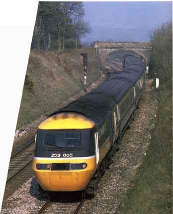
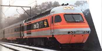
Powercar 43010 leads a 7 + 2 formation on the Manchester-Plymouth
line in April 1987. This is the final design evolved from the models
and the pre production prototype.
POWER-CAR TECHNOLOGY
Each power car of the HST has one Paxman Valenta 12-cylinder Vee turbo pressure-charged and intercooled diesel engine developing 2250hp gross at 1500 rpm. The engine is direct-coupled to a pair of Brush Electrical machine alternators, one for traction and one for the heating, air conditioning and other services. The output from the traction alternator is rectified and supplied to four dc traction motors, one to each axle driving the road wheels through flexible couplings and single-reduction gears. Engine speed and hence power is controlled by the driver in a number of steps, and an electronic regulator maintains a fixed power output corresponding to each controller position irrespective of train speed; the engine in the rear power car is remotely controlled. The diesel engine is water-cooled and the water temperature is kept more or less constant by air drawn and blown through two radiator panels, with separate circuits for the engine jacket and intercooler.
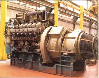
An HST power pack. A Paxman 12-cylinder “Valenta” engine; it
is shown on its transporting cradle coupled to Brush alternators after
overhaul in the Derby works. The turbo-charger and
intercoolers can be seen above the ‘Vee’ formed by the two banks of cylinders.
TRAIN SERVICES
The introduction of high-speed trains on the Paddington Bristol/South Wales services heralded a new era of travel on British Rail. The first trains were introduced with a new timetable on 6 October 1976, for which 27 2+7 sets were provided. They soon settled down to provide fast and reliable services, and were well received by the traveling public. One service, the 17.20 from Paddington to Bristol, achieved a timetabled average speed of 167.9 km/h (104.3 mph) to its first stop at Chippenham, 151 km (94 miles) from London.
Following the success of the South Wales services, it was decided to replace the ageing Deltic locomotives on the London to Leeds/Newcastle/Edinburgh services. Authorization for a batch of 42 8+2 Sets was sought, but this was reduced to 32 sets by the Department of Transport. This meant that some of the semi-fast services would still have to be worked by Deltic locomotives with seven or eight coaches. The full service of HSTs could not be operated until 20 August 1979 because of the disruption caused by the collapse of Penman shields Tunnel. An interim service had started in mid-1978 as sets became available. It was now possible to travel from Kings Cross to Edinburgh in 4 hours and 43 minutes including a stop at Newcastle — an average speed of 135.7 km/h (84.3 mph). At that time there were 88 station-to-station runs at start-to-stop averages varying between 144.8 and 157 km/h (90 and 97.6 mph).
The success of the South Wales service prompted a further batch of 14 2+7 sets for the London-Plymouth Penzance route, which began in October 1979. These were followed by a batch of 18 2+7 sets for the NE/SW cross-country services via Birmingham, commencing in the summer of 1981. A final batch of 4 trains was authorized in January 1980 for the East Coast lines, making a total of 95.
For the maintenance of the trains, new depots were built at Old Oak Common (London), Bristol (St Philips Marsh), Plymouth (Laira), Bounds Green (London), New castle (Heaton), Leeds (Nevill Hill) and Edinburgh (Craigent Each depot has sections for normal cleaning, refueling and maintenance and repair work, and can accommodate full-length trains of nine or ten vehicles as appropriate on one road, under cover. One of the principal features of the Mark 3 vehicles is the modular design of the under-car equipment, which considerably eases the maintenance man’s work. Although the fairings extend downwards towards rail level, easily opened doors reveal the various modules which can be withdrawn, un plugged and replaced for maintenance or in case of failure.
Electrification of the London-Edinburgh/Leeds lines has now released a number of HST sets which have been allocated to other services to replace locomotive-hauled trains, such as Manchester-Poole, Weymouth and through trains from places such as Penzance to Aberdeen.
British Rail’s high-speed train concept was relatively conventional, but even in 1976 it made use of developing hi-tech electronics with plug-in replaceable modules in the traction control and braking functions. New and improved materials were employed in its construction. Particularly interesting were the driver’s cabs, which were built as a complete unit in resin-bonded fiberglass. One worry was the damage that might be caused by striking a solid object at 200 km/h (125 mph). Special tests were made with various thicknesses of material and of the glass for the front windows, with extremely satisfactory results. Today British Rail still operates the fastest diesel-powered trains in the world, and will continue to do so for the rest of this century.
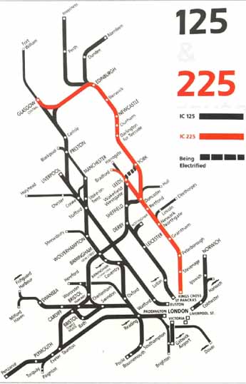
The InterCity Network (ca. early 1990s)
THE AUSTRALIAN CONNECTION
HST technology was sold by British Rail to the New South Wales State Railway Authority and is used on its so-called XS project.
TECHNICAL DETAILS
Technically XPT is an improved and adapted version of the British HST. The standard formation is two power cars and five trailers. Built in Australia by Comeng in corrugated stainless steel, the passenger cars demonstrate the most obvious departure from British practice. They are just under 4 ft longer than the British Mk 3 cars, with a body length of 24.2 m (79 ft 43/4 in) for the same number of second-class seats. The standard of comfort is higher. The BT1O bogie was modified to suit Australian track, but retains the same suspension principles.
Several design improvements were made to the power cars which are 442 mm (17.4 in) shorter than the originals and some 2.5 tons (5500 lb) lighter. The Australian engineers claimed that weight distribution was better than the British version. The same Paxman Valenta engine is used, but de-rated to 2000hp (principally to offset the effects of higher operating temperatures). Also the smaller number of cars and lower top speed do not war rant the full 2250hp of the HSTs.
Rather than being the predicted failure, the XPT has been such a success that extra cars and sets have been required. But all has not been plain sailing, and the volatility of the Australian labor unions has led to some unplanned changes. Immediately the first trains were delivered there was a dispute with the unions over the lack of guard’s accommodation. This resulted in an order for five additional passenger cars with enlarged guard! luggage compartments, which were delivered from Comeng in late 1983. In the first trains the guard had a small area next to the galley in the Type-2 car.
In 1984 Comeng delivered a further five power cars and 10 passenger coaches which, together with the extra passenger/guard’s cars made up six 2+5 sets for revenue- earning service, leaving three power cars and five passenger cars spare. This was the situation until 1985 when SRA ordered a further 12 passenger cars to increase the six sets to the 2+7 formation.
A purpose-built maintenance depot was constructed at Sydney, 5 km (3 miles) south of the terminal station. The depot deals with all running maintenance, facilitated by having the spare vehicles. Although XPTs nominally run as fixed formations, individual vehicles are often taken out of sets for maintenance and are replaced by ones from the pool of spares.
There is no doubt that XPT has made a positive impact, despite controversy on the fare structure, seating and catering. The XPT’s amenities and faster service (still relatively slow by British HST standards) have given impetus to an increase in passengers. On 14 May 1986 the NSW Minister for Transport announced that 14 new high- performance trains ( would be introduced between then and 1996.
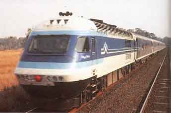
The Australian version of British Rail’s IC125 in its new colors.
The similarity of the styling is immediately apparent.
XPT ( Australia) Specs:
GAUGE: Transmission |
Standard 4 ft 8½ in (1435 mm) Electric |
FORMATION: Power cars: Trailers: |
2+5 (later some 2+6) 2 5 (some 6) |
BUILT: Builder: Number built: Service requirement: |
1980-85 Comeng 15 power and 35 assorted trailer cars 6 sets |
DIMENSIONS: Power car: Trailer car: |
155 m (510 ft) overall 16932 mm (55 ft 6½ in) 24200 mm (79 ft 4¾ in) |
SEATING: Type 1: Type 2: Type 3: |
Variable according to formation 72 64 plus galley and guard’s compartment 40 plus buffet car |
POWER EQUIPMENT: Engine: Alternator: |
Diesel electric Ruston Paxman Valenta 12RP200L - 2000 hp, 1500 rpm Brush BA1001B |
TRACTION MOTORS: Type: |
4 dc series type Brush TNH68—46 |
MAX PERMITTED SPEED: Normal service speed: |
160 km/hr (100 mph) 160 km/hr max |
Political Fallout XPT has been described as a “political” train. In the early 1980s the State Railway Authority (SRA) of New South Wales was undergoing a major revival. Passenger traffic in the years 1975-79 had increased by 14 per cent and freight tonnage by 27 per cent. The SRA claimed that after years of neglect and decline, railways were on the way up. That view was not universally shared by the press or public. The way to get the message across was to have something tangible, and in 1979 the NSW Transport Commission announced that instead of ordering more locomotive- hauled rolling stock it was going for Inter-City XPT trains based on the British HST. This to the Australians was rather like the British Transport Secretary announcing that he was to buy French TGV5 to solve a problem on a particular line of British Rail. The SRA countered its critics by saying that even with a top speed of 160 km/h (100 mph), the much greater acceleration and braking would significantly reduce journey times between Sydney and the country centers. With the state elections due in September 1981, XPT became the target for much political in-fighting between the state premier and the opposition. When the first two vehicles—a power car and one trailer— were handed over with a blaze of publicity on 24 August 1981, there was a large crowd present. The two cars toured New South Wales between then and election day ( 19 September 1981), attracting large crowds at each stop. As a final fling the Country Party claimed that the train would never reach 140 km/h (87 mph), let alone 160 km/h (100 mph). In reply the SRA mounted a series of test runs with one power car, two trailers and a test van during which, in the course of several runs, speeds in excess of 160 km/h were attained. The state premier was re-elected and immediately announced his party’s firm intention to produce “plenty more from where this came from”.
|
IC225 - EAST COAST ELECTRICS
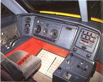
Clean layout of instruments and operating comfort are the
hallmarks of the class 91 locomotive. This is the “front” cab; the one
at the rear has a similar layout. but the windows are vertical.
 A class 91 locomotive at the head of train of Mk4 coaches
with a driving van trailer at the rear. The class 91 normally leads the
trains when traveling north.
A class 91 locomotive at the head of train of Mk4 coaches
with a driving van trailer at the rear. The class 91 normally leads the
trains when traveling north.
Mention was made earlier about releasing IC125 sets to other services following the electrification of the East Coast main line from London to Edinburgh and Glasgow. From the time of British Rail’s modernization plan of 1955, electrification of the East Coast main line had been the preferred option.
A number of proposals had been made, but the advent of the IC125 made the financial case for electrification difficult to prove. For a while British Rail’s operators seemed to be content with the journey times between London and Edinburgh or London and Leeds that were achieved within a maximum speed of 200 km/h (125 mph). With the rapid development of electric traction and by adopting different operating methods, it was clear that a time of 4 hours was practical between London and Edinburgh. The East Coast main line has only slight gradients, is relatively straight — at least south of the border between England and Scotland — and connects few major centers of population. In short it is ideally suited to high-speed operation, as had already been shown by the successful use of the IC125. With new technical developments it was clear that savings could be made on the fixed equipment, overhead lines and signal ling. On 27 July 1984 electrification was at last authorized.
Thirty-one new high-power four-axle electric loco motives, Class 91, and matching sets of new Mk 4 rolling stock have been built. They have a potential for 225 km/h (140 mph). Locomotives and coaches are marshaled into standard formations of 10 vehicles, with the locomotive at one end and a Driving Van Trailer at the other. This method of operation (push-pull) is not a new concept. As long ago as 1967, the principle of propelling eight or more vehicles at speeds of up to 145 km/h (90 mph) had been adopted for the London-Bournemouth line. It was also adopted for the APT, which ran many hundreds of miles at 200 km/h (125 mph) or more. Research and practical tests had shown there was no problem in extending the principle to even higher speeds.
Wiring had to be installed from Hitchin to Leeds, Newcastle and Edinburgh — the stretch between London (Kings Cross) and Hitchin (51.5 km, or 32 miles) had been electrified for suburban services in 1977. With more than 25 years of experience, it was carried out very much more cheaply, and with less environmental impact, than the parallel line between London (Euston), Birmingham, Manchester and Liverpool.
Electric trains began to run to Leeds on 11 August 1988, the full high-speed service commencing in October 1989 and to Edinburgh in May 1991. They set new standards of high-speed running in Britain. At a special demonstration on 26 September 1991, locomotive 91012, with a load of six vehicles weighing 265 tons (260 tons), ran the 632.6 km (393.1 miles) non-stop from London (King’s Cross) to Edinburgh in 3 hours 29 minutes at an average speed of 181.6 km/h (112.85 mph). The maximum speed of 225 km/h (140 mph) was attained over a total distance of 236.6 km (147 miles), while a further 294.5 km (183 miles) were run at speeds between 209 and 225 km/h (1 30-140 mph). Six hours was allowed in 1938 with the steam-hauled Coronation, which rarely exceeded 160 km/h (100 mph). From 30 September 1991, there was a regular service from London to Edinburgh, calling at York and Newcastle, covering the distance in 3 hours 59 minutes — an average speed of 158.8 km/h (98.7 mph).
Equipment Layout of Class 91 Locomotives
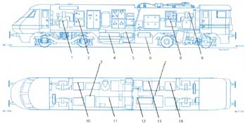
1 Traction motor smoothing choke
2 High voltage cubicle No. 1
3 Rheostatic brake No. 1
4 Transformer
5 cooler group
6 compressor
7 Rheostatic brake No.2
8 High voltage cubicle No. 2
9 Traction motor cooling fan to Electronics cubicle
11 converter
12 Brake control frame
13 Battery box
14 Auxiliary cubicle
THE COACHES
Mk 4 coaches are built to a profile, like the SNCF Grand Contort coaches, which permits “tilt” to be added at a later date if required. The locomotive profile matches but is not, as with the Swedish X2 locomotives, built to tilt (see Chapter 6). The vehicles, built by Metro Cammell (now part of GEC), are the same length as the Mk 3 but run on Schlieren-designed bogies. These too have been subjected to the most stringent riding tests and had to be adjusted before acceptance by British Rail.
It is interesting to reflect that the locomotives were ready before the coaches, and prior to full operation were run with rakes of Mk 3 vehicles. To enable push-pull operation, 10 HSTs were used. One power car was removed and replaced by a Class 91 locomotive. The other power car was modified, the external appearance being altered by the addition of side buffers.
Internally, a TDM system was installed, operating over the existing control cables, allowing the Class 91 to be controlled from the HST cab. Because the HST auxiliary power supply was not compatible with that from the Class 91, the train auxiliaries, air conditioning, and so on were fed from the diesel generator set of the HST power car. Traction power was also available from the HST power car in case of need I
As rakes of Mk 4 vehicles became available during 1989, they replaced the part-HST sets which were re deployed on other services. Full electric operation between London and Leeds was available from October 1989 onwards.
HSTs still operate over parts of the East Coast main line on cross-country workings from the West Country, and of course on through services to Aberdeen and Inverness, Cleethorpes, Hull, and so on.
INTERCITY 225 ( Britain) Specs:
GAUGE: System: |
4 ft 8½ in (1435 mm) 25kv ac 50hz |
FORMATION: Locomotive: Traders: Driving van trailer: |
1+10 1 9 1 |
BUILT: Locomotive: Trailer: Driving van trailer: Number built: |
GEC/BREL BREL as sub-contractor to GEC ( Crewe) GEC Birmingham GEC Birmingham 31 sets |
WEIGHTS: Locomotive: Trailer: Driving van trailer: |
Complete train 476 tons (468.5 tons) 81.5 tons ($0 tons) 40 tons (39.4 tons) 34.5 tons (33.9 tons) |
DIMENSIONS: Width: |
23000mm (75 ft 5½ in) long 2740mm (8 ft 11 in) |
SEATING: First: Standard: |
508 but can vary 46 per vehicle 74 per vehicle |
LOCOMOTIVE: Wheel arrangement: Rating: Peak output: Motors: Type: Maximum speed: Maximum load: Length: Width: Bogie centers: Wheel diameter: Control system: Braking: |
Class 91 Bo-Bo 4530 kW (6075 hp) 4700 kW (6300 hp) 4 de separately-excited GEC 426AZ 225 km/hr (140 mph) $30 tons at 160 km/hr 19400mm (63 ft 7¾ in) 2740mm (8ft 11¾ in) 10500mm (34 ft 5½ in) 1000mm (3 ft 3¼ in) Microprocessor-controlled Thryistor Rheostatic 225 to 45 km/hr (28 mph) Shaft-mounted disc and tread to standstill |
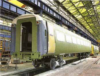
The Mk4 body shell shown on ‘accommodation’ bogies prior
to being fitted out. Note the wide gangway and the sliding plug doors.
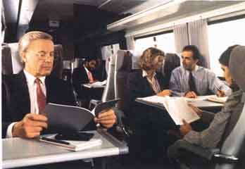
View of the interior of a Mk4 first-class coach. The normal
2+1 seating is employed, and the seats have limited adjustment.
IC225 Locomotives
The 31 new Class 91 electric locomotives were supplied by GEC to a very stringent specification, which included a guaranteed period of trouble-free running before being taken over by British Rail. The mechanical parts were built and the equipment erected in the former British Rail works at Crewe, now owned by BREL. These locomotives are examples of the latest in high technology and are designed to haul and propel trains of up to 520 tons (510 tons) at speeds of up to 225 km/h (140 mph). They weigh 81.5 tons (80 tons) and develop 4530kw (6075hp).
The Class 91 has four separately-excited dc motors mounted in the locomotive body and driving the axles through Cardan shafts and axle-mounted right-angle gear boxes. A disc brake is mounted on an extension of each motor shaft. Electric rhoestatic braking is also provided, and used from the highest speed down to a level where the disc brakes are blended in to take over as the rheostatic brake fades to zero. The electrical energy generated by the motors is dissipated in resistances. Power is regulated in a thyristor converter controlled by microprocessor.
The locomotives are unusual for Europe in having an asymmetric shape. They are normally marshaled at the northern end of trains, so one cab only has a wedge- streamlined form, Streamlining of the other end of the train is provided by a similar form on the Driving Van Trailer (DVT). This is a vehicle with a driving cab and full controls from which the locomotive is operated when pushing the train. Control of the locomotive is achieved electronically along a pair of wires that run the length of the train. Between the DVT and the locomotive there are normally eight of the new Mk 4 coaches.
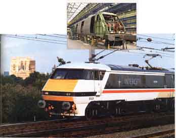
TOP At the opposite end of the train to the locomotive, control
is provided from a driver’s cab in the driving van trailer. This picture
shows a DVT under construction and illustrates the similarity of end
styling to that of the locomotive. BELOW An IC225 locomotive with the
majestic backdrop of York Minster. This point is now
less than 2½ hours’ traveling time from London.